
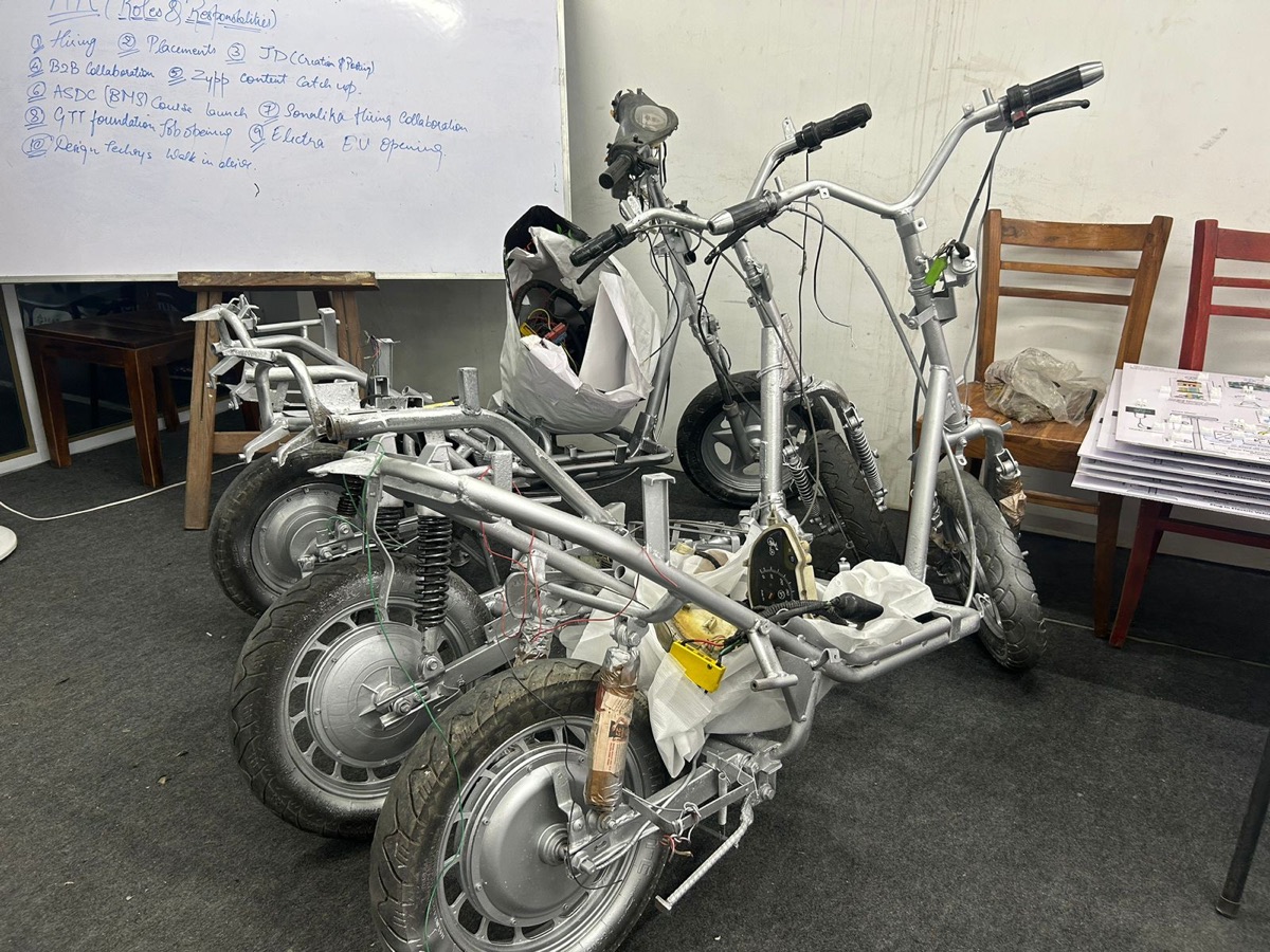
The problem
Battery swapping can cut downtime for fleets of electric two- and three-wheelers, but manual swapping is slow and the heavy packs strain workers. An automated station must align with packs in varying positions, unlock, extract, transfer, insert and lock reliably, quickly and safely. Mechanical design, cycle time and tolerance to misalignment decide whether such a station is practical.
Objectives
- Define pack, vehicle docking tolerance, throughput and safety requirements.
- Design alignment, gripping, extraction, transfer and insertion mechanisms and a pack magazine.
- Use Motion studies to analyse each stage and build the full swap sequence.
- Size actuators and structures, and analyse alignment tolerance stack-up.
- Optimise cycle time and station throughput, and plan validation.
What you need
Tools and toolboxes
- SOLIDWORKS Part, Assembly and Weldments — Station frame, docking guides, gripper, linear axes, lift and magazine racks.
- SOLIDWORKS Motion Study (Motion Analysis) — Motors with segment profiles for each axis, contact during insertion, Event-Based Motion for the swap sequence and torque and force plots; needs SOLIDWORKS Premium or a Simulation Professional or Premium licence.
- SOLIDWORKS Simulation (Static and Frequency) — Frame and gripper stiffness and strength under pack loads and the dynamic effect of accelerations.
- TolAnalyst — Tolerance stack-up from docking guides to pack connector for alignment capability; a manual worst-case and RSS stack in Excel is the alternative.
- SOLIDWORKS Composer — Animated sequence and maintenance instructions from the assembly.
- MATLAB or Excel — Cycle-time model, queue and throughput simulation and actuator sizing.
Software
- SOLIDWORKS 2023 or later (Premium for Motion Analysis)
- SOLIDWORKS Simulation
- MATLAB or Excel
Extra parts and data
- Pack and latch dimensional data — Pack mass, size, latch type and connector alignment needs define the gripper and tolerances; example values must be labelled if real data is not available.
Key concepts
- Swap cycle time
- The time from vehicle docked to vehicle released with a charged pack, made of alignment, unlock, extraction, transfer, insertion, lock and verification.
- Event-Based Motion
- In Motion Analysis, tasks are triggered by sensors or earlier tasks, so a whole multi-axis sequence can be modelled as it would run in a controller.
- Tolerance stack-up
- The combined effect of part and positioning tolerances on how well the pack connector aligns. Worst-case and statistical (RSS) stacks give limits.
- Throughput
- Swaps per hour, set by cycle time, the number of bays and charged packs available, and arrival patterns of vehicles.
Step-by-step guide
- 1
Define requirements and research questions
Use an example swappable pack of 25 kg for an electric two-wheeler or 40 kg for a three-wheeler, with stated dimensions and latch type. Define docking tolerance: vehicle position ±30 mm and ±3 degrees after a guide rail. Set an example throughput target and maximum cycle time, and safety rules for people near the station. Write research questions on cycle time, tolerance capability and throughput.
Checkpoint: A requirements document with pack data, tolerances, throughput target and research questions.
- 2
Choose the station concept
Compare a side-extraction station where the pack slides out sideways, a bottom-drop station and a top-lift station. Score them for vehicle compatibility, mechanism complexity, footprint, safety and cycle time. Choose one and sketch the sequence of stages and axes. Define the magazine for charged packs, such as a vertical rack served by a lift, and how packs reach chargers. Note which vehicle designs each concept would suit.
Checkpoint: A concept matrix and a stage-by-stage sequence sketch with axes listed.
- 3
Design docking and alignment
Model guide rails and a wheel cradle that bring the vehicle to a known position. Add a final alignment stage, such as tapered locating pins entering bushes on the vehicle or pack, that corrects remaining misalignment. Use TolAnalyst or an Excel stack to estimate alignment at the pack connector from the docking tolerance and part tolerances. Adjust chamfers and pin tapers so the stack fits the connector's float.
Checkpoint: A tolerance stack showing worst-case or RSS misalignment within the connector's allowed float.
- 4
Design gripper and extraction
Design a gripper that engages handles or features on the pack, operates the latch release and withdraws the pack along its rails. Model the latch interface and the force needed to release it. Add a linear axis with a ball screw or belt drive for extraction. Use Mass Properties for moving masses. Make sure the gripper cannot drop a pack if power fails.
Checkpoint: A gripper and extraction axis that fits the pack, with a fail-safe hold concept.
- 5
Design transfer and magazine
Design a transfer axis that moves the pack from the vehicle to the magazine lift and back, and the lift serving rack positions with chargers. Use Weldments for frames and select example linear guides. Keep travel short to cut cycle time. Check clearances during transfer with Interference Detection at intermediate positions and with Collision Detection while dragging. Leave space for charger cables and cooling air around each rack position.
Checkpoint: A complete station assembly with no interference along the transfer path.
- 6
Model each stage in Motion
Create a Motion Analysis study for each stage: alignment, unlock and extraction, transfer, insertion and lock. Drive axes with motors using segment profiles and realistic acceleration limits. Add contact between pack rails and guides and between connector halves during insertion. Plot axis forces, torques and powers, and stage durations. Check that insertion force stays below the connector's allowed limit at the worst misalignment, and that the latch closes fully at the end of the stroke.
Checkpoint: Stage-level motion results with forces and durations, including insertion with contact.
- 7
Build the full sequence
Use Event-Based Motion to link tasks: each axis move is triggered by a sensor or the end of the previous task, mirroring a controller sequence. Overlap tasks where safe, such as moving the lift to the charged pack while extraction is in progress. Run the full swap and record total cycle time and the critical path of tasks. Mark which tasks are waiting on others.
Checkpoint: A full swap simulation with total cycle time and the critical path identified.
- 8
Size actuators and structure
From motion results, take peak and RMS loads for each axis and size motors, gearboxes or screws with margin. Add brakes to vertical axes. Run static studies of the frame and gripper under pack weight and dynamic loads, check deflection at the connector against its float and check frequencies against motion excitation. Refine meshes at mounts. Record the selected parts in an actuator table.
Checkpoint: Actuator ratings above requirements, deflection within float and safety factors above targets.
- 9
Optimise cycle time and throughput
Build a cycle-time model in MATLAB or Excel from the motion results, with acceleration limits, distances and overlaps as variables. Optimise motion profiles and task overlaps for the shortest time within limits. Then simulate throughput with a simple queue model: vehicle arrivals, number of bays and charged pack availability. Report swaps per hour and waiting time. Check the model against the full sequence result first.
Checkpoint: An optimised cycle time and a throughput estimate with queue waiting times for stated arrival rates.
- 10
Assess failure modes and safety
List failure modes: misaligned docking, latch not releasing, pack dropped, power loss mid-swap, connector damage. For each, define detection, response and recovery. Plan guarding, light curtains and an emergency stop. Note that pack handling and electrical safety must meet applicable standards, including AIS-156 for the pack, and that the station design needs a formal risk assessment. Rank each by severity and likelihood.
Checkpoint: A failure-mode table with detection, response and recovery for each mode.
- 11
Document and plan validation
Make a general arrangement drawing, an animated sequence in SOLIDWORKS Composer and a report with requirements, concept choice, tolerance analysis, motion results, actuator sizing, cycle time, throughput and failure modes. Plan validation on a single-axis or scaled rig, comparing measured stage times and forces with simulation, and a docking repeatability test. Set targets such as stage time within 10 per cent of prediction and successful docking across the tolerance range.
Checkpoint: Drawings, an animation, a report and a validation plan with measurable targets.
Testing & validation
- Tolerance stack shows alignment within connector float.
- Insertion succeeds with contact in the Motion study at worst-case misalignment.
- Actuator ratings exceed required loads with margin.
- Structural deflection and stresses meet targets.
- Cycle-time model matches the Event-Based Motion result before optimisation.
Expected results
A complete automated swap station mechanism with docking, gripper, transfer and magazine, stage and full-sequence motion results, sized actuators, a tolerance analysis, an optimised cycle time and throughput estimate, and a failure-mode and validation plan.
Research angle for your PhD
Automated swapping for Indian two- and three-wheeler fleets is an active area, but open studies on mechanism design, tolerance capability and throughput are limited. A study can link CAD-based motion and tolerance analysis to a throughput model, identify which stages dominate cycle time, quantify how docking tolerance drives mechanism complexity and validate key stages on a rig. The contribution is a design and evaluation method for swap stations.
Take it further
- Design a universal gripper for packs of different sizes.
- Add thermal management of the charged pack magazine with Flow Simulation.
- Model a vision-based alignment sensor and its mounting.
- Build and test a scaled single-axis rig.
Viva and review questions
What sets the swap cycle time?
The critical path of the sequence: alignment, unlock, extraction, transfer, insertion and lock, minus whatever can safely be overlapped, such as preparing the charged pack during extraction.
How did you check alignment capability?
With a tolerance stack-up from docking guides through the station and pack to the connector, worst-case and RSS, compared with the connector's allowed float.
Why use Event-Based Motion?
It triggers each task from sensors or the end of previous tasks, like a real controller sequence, so overlaps and the total cycle time can be studied.
What happens if power fails mid-swap?
Brakes hold vertical axes, the gripper holds the pack mechanically, and recovery steps let an operator complete or reverse the swap safely.
Learn it at DIYguru
These DIYguru courses and programmes teach what this project needs.