
The problem
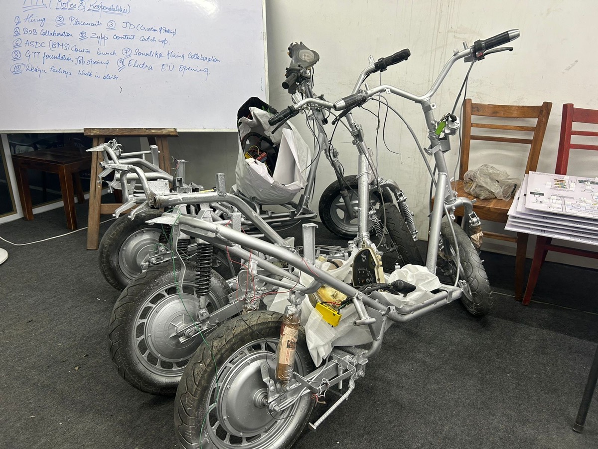
Electric motorcycles deliver high torque from standstill, which makes the rear squat or extend sharply on acceleration, and strong regenerative and friction braking makes the front dive. Anti-squat and anti-dive geometry control these pitch motions. The drive type changes the answer: a hub motor reacts torque differently from a chain or belt drive. Students need a clear method to compute and tune these properties.
Objectives
- Model rear swingarm, drive sprockets or pulleys and front fork geometry with key points as parameters.
- Compute anti-squat through rear travel for chain or belt and for hub-motor drive.
- Compute anti-dive for the front under braking, including regenerative braking at the rear.
- Tune pivot and sprocket positions and compare designs against stated targets.
What you need
Tools and toolboxes
- SOLIDWORKS Layout sketch and Blocks — Side-view kinematic layout of swingarm pivot, axle, sprockets, chain line, contact patches and centre of gravity, used for graphical instant-centre construction.
- SOLIDWORKS Assembly and Motion Study — Swingarm and fork moved through travel by a motor at the axle, with plotted positions of key points; Motion Analysis (SOLIDWORKS Premium) adds force results.
- Design Tables — Swingarm pivot height, sprocket sizes and fork rake variants.
- Excel or MATLAB — Anti-squat and anti-dive calculations from exported point coordinates, and plots against travel.
Software
- SOLIDWORKS 2023 or later
- Excel or MATLAB
Extra parts and data
None beyond the software above.
Key concepts
- Anti-squat
- The percentage of load transfer reacted through the suspension geometry rather than by compressing the spring. 100 per cent means the rear neither squats nor extends under acceleration.
- Squat line construction
- For a chain drive, the line from the rear contact patch through the intersection of the swingarm line and the chain's upper run, compared with a line to the CG height above the front contact, gives anti-squat.
- Hub-motor reaction
- With a hub motor, drive torque reacts directly into the swingarm, so anti-squat depends on swingarm angle rather than a chain line.
- Anti-dive
- Under braking, front fork geometry and brake reaction set how much the front compresses. Telescopic forks usually have little anti-dive from geometry alone.
Step-by-step guide
- 1
Define vehicle and drive options
Use an example electric motorcycle: wheelbase 1,400 mm, mass with rider 260 kg, CG height 650 mm, rear travel 120 mm and front travel 120 mm, all stated as examples. Define three drive options: mid-mounted motor with chain, mid-mounted motor with belt with a different pulley ratio, and rear hub motor. Set targets, for example rear anti-squat near 100 per cent at sag, and explain why you chose them with reference to rider comfort and traction.
Checkpoint: A requirements sheet with vehicle data, three drive options and anti-squat targets with reasons.
- 2
Build the side-view layout
In a Layout sketch, draw the ground line, wheel circles, contact patches, CG point, swingarm pivot, axle, front and rear sprockets or pulleys, and the chain upper run as a tangent line. Use global variables for pivot height, sprocket radii and CG position. Make the swingarm a block that rotates about its pivot so the axle can move through travel while the chain line stays tangent.
Checkpoint: Dragging the swingarm block moves the axle through travel and the chain line remains tangent to both sprockets.
- 3
Construct anti-squat graphically
For the chain drive, add construction lines: extend the swingarm line and the upper chain run to their intersection, then draw a line from the rear contact patch through that point to the front axle vertical. Compare its height there with CG height to get anti-squat percentage. Add a dimension that reports this height. For the hub-motor drive, use the swingarm line itself from the contact patch side.
Checkpoint: A layout that shows anti-squat percentage at sag position, checked against a hand calculation from coordinates.
- 4
Build the assembly for motion
Model simple parts for frame, swingarm, sprockets and fork from the layout. Assemble with a concentric mate at the swingarm pivot and a slot or concentric mate for the fork sliders. Add sketch points on the contact patches, chain tangent points and axle. In a Motion study, drive the rear axle vertically with a linear motor through full travel and the fork through its travel separately.
Checkpoint: The Motion study moves both ends through full travel without mate errors.
- 5
Export coordinates and compute
Use Results and Plots to record the X and Z positions of axle, pivot, sprocket centres and contact patch through travel, then export to CSV. In Excel or MATLAB, recompute chain tangent lines, the instant force centre, and anti-squat at each step. Plot anti-squat against wheel travel for chain, belt and hub motor. Check the sag-position value matches the layout result.
Checkpoint: Anti-squat curves for all three drives, with the sag-position values matching the layout within 1 per cent.
- 6
Compute anti-dive
For the front, compute anti-dive from fork rake, trail and the brake reaction path, and note that a conventional telescopic fork gives little geometric anti-dive. For the rear under regenerative braking, compute anti-rise from the brake reaction; with a mid motor and chain, regenerative braking reverses chain tension, so the lower chain run sets the line. Plot both against travel.
Checkpoint: Anti-dive and rear anti-rise curves with the regenerative braking case clearly separated.
- 7
Tune the rear geometry
Use a Design Table to vary swingarm pivot height, front sprocket size and swingarm length within packaging limits. For each, recompute anti-squat at sag and the slope of the curve through travel. Find designs that meet the target at sag with a gentle slope. Check that chain growth through travel stays within what a tensioner or slack can handle. Keep every variant in the same results sheet so trends are easy to see.
Checkpoint: A tuned design meeting the anti-squat target at sag, with chain growth tabulated and acceptable.
- 8
Estimate pitch response
Using a simple quasi-static model, estimate rear spring compression under an example full-torque launch for each design: load transfer from acceleration, the share reacted by geometry from anti-squat and the rest by the spring through the leverage ratio. Do the same for front compression under hard braking. Compare pitch angle between designs. Note that a dynamic multibody model would be needed for transient behaviour.
Checkpoint: Predicted squat and dive values for each design, showing the effect of the tuned geometry.
- 9
Check sensitivity
Vary CG height by ±50 mm and mass by a rider-only versus rider-plus-passenger case, since anti-squat depends on CG height. Plot how anti-squat at sag shifts. A design robust to load changes is often better than one tuned perfectly for a single load. Record the sensitivity for each drive option. Repeat the check with the battery placed higher or lower in the frame, since battery position is the main lever an EV designer has on CG height.
Checkpoint: A sensitivity plot of anti-squat against CG height and load for each drive.
- 10
Drawings and report
Make a geometry drawing with all hard points, sprocket sizes and pivot heights for the chosen design. Write up the method, layout and motion results, drive comparison, regenerative braking effects, tuning and sensitivity. State limits: rigid parts, quasi-static load transfer, no tyre deformation. Recommend validation with suspension potentiometers on a prototype during launch and braking tests. Include a table of anti-squat at sag for each drive option on the drawing sheet.
Checkpoint: A hard-point drawing and report with anti-squat and anti-dive curves for each drive option.
Testing & validation
- Graphical layout and computed anti-squat agree within 1 per cent at sag.
- Chain tangent lines remain correct through travel.
- Pitch estimates follow the expected trend with anti-squat.
- Sensitivity to CG height and load reported.
Expected results
Anti-squat and anti-dive curves through travel for chain, belt and hub-motor drives, including the regenerative braking case, a tuned rear geometry and estimates of pitch under launch and braking.
Research angle for your M.Tech thesis
Electric drivetrains change the classic chain-line picture: hub motors react torque through the swingarm, and regenerative braking reverses chain tension. A study can quantify anti-squat and anti-rise for each drive type under both traction and regeneration, and propose geometry rules for electric motorcycles. Comparison with measured suspension motion on a vehicle and a dynamic model would make the work publishable.
Take it further
- Build a dynamic multibody model to study transient pitch and wheel hop.
- Compare a linkage front suspension designed for anti-dive.
- Add traction control torque profiles and study their effect on squat.
- Measure squat on a prototype with potentiometers and compare.
Viva and review questions
Why does a hub motor change anti-squat?
Its reaction torque goes straight into the swingarm, so there is no chain force line. The swingarm line and torque reaction alone set anti-squat.
What happens to anti-squat under regenerative braking with a chain?
The chain tension moves to the lower run, so the force line changes and the rear tends to rise or squat differently, which is why I computed an anti-rise curve for regeneration.
Why is 100 per cent anti-squat not always the goal?
Some squat or extension can help traction or feel, and anti-squat changes through travel and with load, so designers choose a target with a gentle curve rather than a single value.
How did you verify your calculations?
By constructing anti-squat graphically in the layout at sag and comparing with values computed from exported coordinates, which agreed within 1 per cent.
Learn it at DIYguru
These DIYguru courses and programmes teach what this project needs.