
Hardware delivered to your door
Program a real EV control board from home.
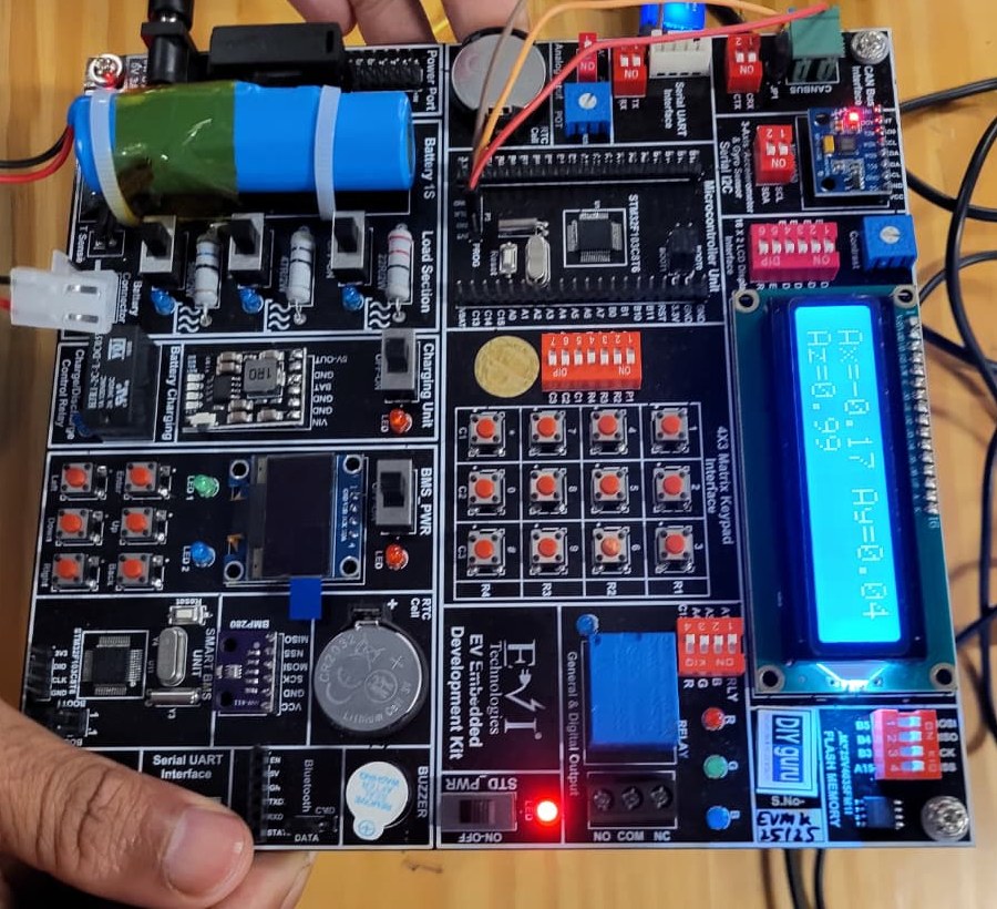
The EV Embedded Development Kit puts an STM32 controller, a Smart BMS unit, CAN bus, sensors and displays on one labelled board. Built by EVI Technologies and DIYguru, it takes you from your first blinking LED to battery monitoring, motor control and vehicle networking.
- STM32F103 microcontrollers on one board
- 2
- STM32F103 microcontrollers on one board
- guided experiments
- 15+
- guided experiments
- interfaces: GPIO, ADC, UART, I2C, SPI, CAN
- 6
- interfaces: GPIO, ADC, UART, I2C, SPI, CAN
- low-voltage cell, safe on a study desk
- 1S
- low-voltage cell, safe on a study desk
₹10,000 + GST
₹11,800 in total, including 18% GST · secure payment by Razorpay (UPI, cards, net banking)
Why this kit
Everything an EV control unit does, on one board
Videos explain embedded systems. This board lets you do the work: write the firmware, flash it, watch it fail, debug it and make it right.
A real BMS on your desk
A dedicated Smart BMS unit with its own STM32, a battery cell with temperature sensing, charging, a charge/discharge relay and three switchable loads. Watch a pack being charged, loaded and protected.
CAN bus, the language of every EV
An onboard CAN interface with screw terminals. Pack, send, filter and debug the same kind of frames a BMS sends to a vehicle control unit.
Two microcontrollers, like a real vehicle
One STM32F103C8T6 as the main controller and a second as the BMS unit, so you write firmware for separate control units and make them work together.
Nothing to wire before you start
Every block is built, labelled and isolated with DIP switches. Switch on the peripheral you want and spend your time on firmware, not on loose jumper wires.
Sensors that matter in a vehicle
A 3-axis accelerometer and gyroscope, a BMP280 pressure and temperature sensor, an analog input, battery temperature sensing and a real-time clock.
Two displays and real controls
A 16×2 LCD, an OLED for the BMS, a 4×3 matrix keypad, six navigation buttons, RGB LEDs, a buzzer and a relay output. Build interfaces people can actually use.
What you get
What's on the board
Each block is printed with its name and pin labels, so you can see how the circuit maps to your code.
Controllers
- STM32F103C8T6 microcontroller unit (Arm Cortex-M3)
- Second STM32F103C8T6 as the Smart BMS unit
- Reset, boot-mode and programming headers
- Power port and master on/off switch
Battery and BMS
- 1S battery with connector and T-sense input
- Load section: three switchable resistive loads with LEDs
- Battery charging unit with its own switch
- Charge/discharge control relay
- BMS power switch, OLED and six navigation buttons
Communication
- CAN bus interface with screw terminal
- Serial UART interface
- Bluetooth module header
- I2C and SPI buses to the onboard devices
Sensors and memory
- 3-axis accelerometer and gyroscope (MPU6050, I2C)
- BMP280 pressure and temperature sensor
- Analog potentiometer input
- RTC with CR2032 backup cell
- SPI flash memory
Displays and outputs
- 16×2 LCD with contrast control
- 4×3 matrix keypad
- General output relay (NO / COM / NC)
- RGB LEDs and a buzzer
- Motor driver for PWM motor-control experiments
What you'll build
15 experiments, from first blink to RTOS
Each one builds on the last, so by the end you have combined sensing, control, communication and protection in working firmware.
- 01
GPIO and LED patterns
Configure clocks and pins, then drive LED sequences. Your first STM32 program.
- 02
Keypad and buttons
Scan the 4×3 matrix, debounce inputs and build a standby → active → fault state machine, the way EV controllers change state.
- 03
ADC and analog sensing
Read the potentiometer through the ADC and work out resolution and reference voltage. Every voltage and temperature in an EV passes through an ADC.
- 04
PWM and LED dimming
Set up timers, change the duty cycle and see how power output is controlled.
- 05
UART communication
Send data between the controller and your PC to monitor and debug a running system.
- 06
I2C sensor integration
Read motion from the MPU6050, then process and show it in real time.
- 07
SPI devices
Read the BMP280 and store data in external memory, using the same bus BMS front-end chips use.
- 08
LCD and OLED dashboards
Show live readings and let the user move through menus.
- 09
Motor control
Control speed and direction with PWM, the principle behind every EV motor controller.
- 10
Battery monitoring
Measure the cell under switchable loads and control charging and discharging.
- 11
Safety and alert systems
Build overcurrent, tilt and temperature alerts that act through the relay, buzzer and LEDs.
- 12
CAN messaging
Pack battery data into CAN frames, transmit it, then filter and decode it. Standard and extended frames.
- 13
Bluetooth link
Send live readings wirelessly to a phone or laptop.
- 14
Real-time clock and logging
Timestamp readings and keep them in flash or EEPROM memory.
- 15
RTOS implementation
Split the work into real-time tasks, as production BMS and motor-controller firmware does.
Why it matters
What you practise here is what runs inside an EV
| Skill | On the kit | In a vehicle |
|---|---|---|
| ADC | Potentiometer and battery readings | Cell voltage, pack current and temperature sensing in the BMS |
| PWM and timers | LED dimming and motor speed | Motor speed control, cooling fans and inverter switching |
| CAN | Onboard CAN interface | BMS, motor controller, charger and dashboard talking to the VCU |
| SPI | BMP280 and flash memory | BMS analog front-end chips reading cell voltages |
| I2C | MPU6050 motion sensor | Current and power monitors, displays and EEPROM |
| UART and Bluetooth | PC serial link and Bluetooth header | Debug consoles, service tools and connected-vehicle links |
| State machines | Keypad-driven operating modes | ECU start-up, self-test, active, fault and shutdown modes |
Tools
The software engineers use
- STM32CubeIDE
- Configure and write firmware for the STM32, and debug it in real time.
- Embedded C
- The language used for production EV firmware.
- Proteus
- Simulate a circuit before you run it on hardware.
- FreeRTOS
- Move on to real-time, multi-task firmware.
Who it's for
Built for anyone serious about EV electronics
Engineering students
Electrical, electronics, mechanical or computer science. Build a portfolio your college labs can't give you.
Diploma and ITI learners
Move from theory to programming real hardware, one experiment at a time.
Working professionals
Moving from automotive, electronics or IT into EV firmware, BMS or controls.
Our learners
Practise at home what you see in live classes, and keep building after a workshop ends.
Learn with it
Pair the kit with a programme or course
The kit is sold separately and works with every programme and course below. Those closest to embedded systems, batteries and motor control are listed first.
Programmes
- Post Graduate Certification Programme In Electric Vehicle & Embedded System Advanced Engineering
- Advanced Nanodegree Certification Program in Embedded Systems Design & Development
- Advanced Nanodegree Certification Program in ADAS & AUTOSAR
- Advanced Nanodegree Certification Program in Battery and BMS Design, Analysis, & Simulation
- PCP in Battery Tech & Powertrain
- PCP in EV Embedded System
- PCP in Motor Drive & Control System
- PCP in EV Electrical Design & Simulation
- M.Tech in Electric Vehicle Technology
- Advanced Nanodegree Certification Program in EV Engineering, Design, Simulations, and Analysis
- Advanced Nanodegree Certification Program in EV Engineering, Automotive Design, Development, & Dynamic Analysis
- Adv. Nanodegree in EV Business
- Adv. Nanodegree in Data Science
- PCP In Industry Ecosystem
- PCP in EV Automotive Design & Simulation
- PCP in Charging Tech & Hydrogen Fuel Cell
- PCP in Data Science
- PCP in Sales & Business
- CEVT - Certified Electric Vehicle Training Programme
- Open Learning Program
Courses
- BMS Course
- Certification Course in Advanced BMS and Modeling & Simulation for EVs
- Certification Course in AUTOSAR for EVs: Standards & Software Architecture
- Certification Course in Embedded Systems Design with STM32 & ARM Cortex-M
- Certification Course in EV Battery Pack Design & BMS Protection Modeling
- Certification Course in Motor & Drive System for EVs: Design & Optimization
- Electric Vehicle Essentials 1: Industry Ecosystem & Battery Technology
- Electric Vehicle Essentials 2: Motors, Electrification and Charging Systems
- Embedded Systems Certification Course: Embedded C, 8051, Arduino & Simulation
- EV Engineering Mastercourse Part 2 : Powertrain, BMS, Charging & System Standards
- Fundamental of AUTOSAR Engineering
- Advanced Certification Course in EV Design & Simulation using MATLAB
- Advanced Control Systems for EV: MATLAB for Design & Implementation
- Advanced EV Engineering: Numerical Analysis, EVs, HEVs, & Heavy Vehicles
- Advanced Power Electronics for EV Applications
- Autodesk Alias Certification Program
- Basic Control Systems for EV: MATLAB for Design & Implementation
- Certificate in Electric Vehicle Technology and Business Management
- Certification Course in 2W & 4W EV Design & Modeling with SOLIDWORKS
- Certification Course in 2W EV Design & Modeling with SOLIDWORKS
- Certification Course in Advanced ANSYS for EV Engineering
- Certification Course in Advanced Driver Assistance Systems (ADAS) for EVs
- Certification Course in Advanced EV Charging Technology
- Certification Course in Advanced Powertrain Development for Electric Vehicles
- Certification Course in Advance Vehicle Dynamics
- Certification Course in ANSYS: From Fundamentals to Structural Analysis
- Certification Course in Automotive Sketching and Drawing
- Certification Course in CATIA V5 – 3D Modeling & Drafting
- Certification Course in Electronics & Circuit Design for EV Applications
- Certification Course in Fundamentals of Vehicle Dynamics
- Certification Course in Hydrogen Fuel Cell Technology for Electric Vehicles
- Certification Course in MATLAB - Simulink
- Certification Course in MATLAB-SIMULINK, QSS & Advisor Toolbox for EV Design
- Certification Course in Solar Power Plant Design and Implementation
- Certification in Advanced Communication Applications Using ARM Cortex
- Certified Electric Vehicle Technician (CEVT) Program
- Drop-in Live Sessions
- Electric 2-Wheeler (E-Scooter/E-Bike) Diagnosis and Service Certification
- Electric Vehicle Fundamentals Certification Program
- Electric Vehicle Fundamentals & Project-Based Internship Certification Program
- EV Course for MTech
- EV Engineering Mastercourse Part I: EV Fundamentals & Core Components
- Hands-On 4 Wheeler Electric Vehicle Systems & Component Demonstration
- LIVE Class Planner - DEMO
- Post Graduate Certification in Electric Vehicle Technology
Questions
Before you order
What does the kit cost?
₹10,000 + 18% GST, so you pay ₹11,800 in total. It is a one-time payment by UPI, card or net banking through Razorpay.
Can I buy the kit without joining a programme?
Yes. Anyone can order it from this page. It is also sold separately for learners on our programmes and courses, so it is not part of a course fee.
Which microcontroller does it use?
The STM32F103C8T6, an Arm Cortex-M3 device. The board has two of them: one as the main controller and one as the Smart BMS unit.
Do I need to solder or wire anything?
No. The blocks are already built and labelled, and DIP switches connect or isolate each peripheral. You will connect the board to your laptop to program it.
Do I need experience in embedded systems?
No. The experiments start with GPIO and LED control and build up to CAN, motor control, battery monitoring and RTOS. Basic electronics and some C will help you move faster.
Is it safe to use at home?
The board runs from a single low-voltage cell, not a high-voltage traction pack. Treat the lithium cell with normal care, and follow the polarity markings and experiment instructions.
What do I need besides the kit?
A Windows, macOS or Linux laptop that can run STM32CubeIDE.
How and when will it be delivered?
Enter your delivery address with PIN code at checkout. Our team contacts you within one working day of your order to arrange delivery, and your dashboard shows the courier and tracking number once it ships.
What if the kit arrives damaged or with a part missing?
Raise a support ticket from your dashboard with your order details and photos, and our team will take it from there.
Can I return it for a refund?
The DIY hardware kit is not refundable. Please read the refund policy before you order.
Get the kit on your desk.
₹10,000 + GST. Our team contacts you within one working day to arrange delivery.