
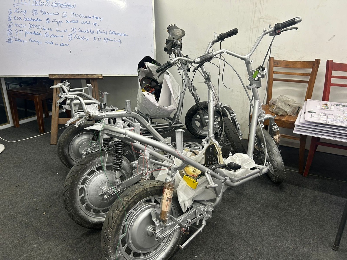
The problem
Folding stems make e-scooters portable, but a latch that loosens or fails while riding is a serious safety risk. The mechanism must be quick to use, free of play, and strong under braking and pothole loads. Students learn how to combine kinematics, a positive locking principle and a strength check in one compact design.
Objectives
- Define folded and unfolded geometry, operating force and load cases.
- Design a hinge and an over-centre or cam latch with a secondary safety catch.
- Simulate folding and locking with a Motion study, including latch force.
- Check hinge pin, latch and stem joint strength under example riding loads.
What you need
Tools and toolboxes
- SOLIDWORKS Part and Assembly — Stem, hinge block, latch lever, cam, safety catch and pins, with mates for hinge and lever motion.
- Advanced mates (Angle Limit, Distance Limit) — Fold range limits and latch stroke stops.
- SOLIDWORKS Motion Study — A rotary motor or force on the stem and latch lever, springs on the catch and contact between cam and stem; Motion Analysis needs SOLIDWORKS Premium or the Motion add-in licence.
- SOLIDWORKS Simulation (Static) — Hinge pin shear, latch stress and stem joint under braking and impact loads.
- Toolbox — Standard pins, bolts and washers.
Software
- SOLIDWORKS 2023 or later
- SOLIDWORKS Simulation
- Excel
Extra parts and data
- 3D printer access — A printed prototype of the latch helps check feel and play before machining metal parts.
Key concepts
- Over-centre latch
- A lever that moves past a straight-line position so that the clamping force holds it closed. It needs an external force to open.
- Secondary safety catch
- A second, independent lock that keeps the latch closed even if the main lever is knocked, so a single failure does not fold the stem.
- Play elimination
- A wedge or cam that pulls the joint tight removes free movement that would otherwise cause rattle and fatigue.
- Load cases
- Hard braking pushes the handlebar forward and down, and a pothole adds vertical impact. Each creates a bending moment at the hinge.
Step-by-step guide
- 1
Set requirements and load cases
Define an example scooter: stem length 1.0 m from deck to handlebar, folded length under 1.1 m, folding time under 5 seconds and a lever operating force a person can apply comfortably by hand. Define load cases as examples: a horizontal handlebar force during hard braking, a vertical pothole impact on the front wheel and a rider pulling up on the bar. Note that product standards for personal light electric vehicles set test loads, which you should check.
Checkpoint: A requirements and load-case table, with each load labelled as an example to confirm against the applicable standard.
- 2
Choose the locking concept
Sketch two or three concepts: an over-centre lever pulling a hook, a rotating cam collar, and a sliding sleeve. Score each for play elimination, ease of use, number of parts and failure mode. Choose one with a positive mechanical lock plus an independent safety catch. Record why each concept was rejected. Include a quick sketch of how each concept is operated with one hand while the other holds the scooter.
Checkpoint: A concept matrix with a chosen mechanism and a written failure-mode argument.
- 3
Model the hinge and latch
Model the hinge block on the deck neck and the stem lower clevis, joined by a hinge pin from Toolbox or a custom pin. Model the latch lever, its pivot and a hook or cam face that pulls the stem tight against a stop. Make the stop faces angled slightly so the latch draws them together to remove play. Use an aluminium alloy for blocks and a heat-treated steel for pins.
Checkpoint: Parts rebuild with the latch geometry controlled by a few key dimensions.
- 4
Assemble with limits
Fix the deck. Add a concentric mate on the hinge pin and an Angle Limit mate between stem and deck from upright to folded. Mate the lever with concentric pivots and a limit on its rotation. Add the safety catch with its own pivot. Check by dragging that the stem folds and the lever moves through its over-centre position. Confirm that the assembly has exactly the degrees of freedom you expect before starting the motion study.
Checkpoint: Dragging moves the stem from upright to folded within limits, and the lever passes over centre.
- 5
Simulate folding
In a Motion study, drive the stem with a rotary motor from upright to folded and back. Turn on gravity. Plot the angle against time and check the folded position clears the deck and rear mudguard. Use Interference Detection or Collision Detection at the folded position. Adjust hinge pin position if the handlebar hits the deck. Also check the folded scooter can stand or be carried, and that the handlebar latch hook meets the rear catch.
Checkpoint: A motion animation that folds and unfolds with no collisions.
- 6
Simulate latch operation
Using Motion Analysis, add solid body contact between cam or hook and stem stop faces and a spring on the safety catch. Apply a force or motor to the lever and plot the lever force needed to close it as it passes over centre. Without Motion Analysis, estimate the force by a free-body calculation at a few positions. Compare with your comfort target.
Checkpoint: A lever force curve that peaks below the comfort target and shows the over-centre point.
- 7
Check hinge and latch strength
In a static study, apply the braking load at the handlebar with the latch closed and the deck fixed. Use pin connectors or bonded contact between pin and bores, and no-penetration contact between stop faces and latch parts. Refine mesh at pin bores and latch contact areas. Check factor of safety against yield. Repeat for the pothole and pull-up cases.
Checkpoint: Factor of safety above an example 2 in every load case at a converged mesh.
- 8
Check what happens if the latch is open
Simulate the safety catch alone holding the stem with the main lever open, under the braking load. The design aim is that the catch keeps the stem from folding long enough for the rider to stop. If the catch fails in the model, strengthen it or change the concept. Record this failure-mode check in the report. Use the same mesh refinement and contact settings as the main latch study so the two results are comparable.
Checkpoint: The safety catch alone resists the braking load without yielding in the model.
- 9
Prototype and test feel
Print the latch parts on a 3D printer at full size or scale to check lever feel, how easily the catch engages and whether play remains when closed. Use the printed model to refine finger clearances. Note that printed parts are only for fit and feel; strength must come from metal parts and testing. Note any changes made after printing and update the CAD model before the strength checks are repeated.
Checkpoint: A printed prototype that closes with no visible play and an engaging catch.
- 10
Drawings and report
Make drawings of the hinge block, lever and pins with tolerances on pin bores and fits, using ISO 286 fit notation such as H7/g6 where needed, and surface finish on stop faces. Write up requirements, concept choice, motion results, strength checks, safety catch check and prototype findings. Recommend a physical static and fatigue test before any rider use. Specify heat treatment and hardness for the pins and a corrosion-resistant finish for exposed parts.
Checkpoint: Toleranced drawings and a report that includes the failure-mode argument and test plan.
Testing & validation
- Fold and unfold animation shows no collisions.
- Lever force stays below the comfort target.
- Static study factor of safety above target in all load cases, with mesh convergence at pin bores.
- Safety catch alone resists the braking load in the model.
Expected results
A folding stem mechanism with an over-centre latch and safety catch, motion results for folding and lever force, strength checks for three load cases and a printed prototype for feel.
Take it further
- Run a fatigue study with repeated braking loads.
- Add a sensor to detect an unlatched stem and block motor power.
- Compare an aluminium and a steel hinge block for mass and safety factor.
- Design a carry handle and folded locking hook.
Viva and review questions
Why include a secondary catch?
So that a single failure, such as the main lever being knocked open, does not let the stem fold while riding.
How does the latch remove play?
The cam or hook pulls angled stop faces together as the lever closes, so the joint is preloaded and cannot move.
How did you model the pin joint in Simulation?
With a pin connector or bonded pin in bores and no-penetration contact at stop faces, with mesh refined at the bores.
Why is a printed prototype not enough?
Printed plastic does not have the strength or wear behaviour of the metal parts. It checks fit and feel only; strength needs metal prototypes and tests.
Learn it at DIYguru
These DIYguru courses and programmes teach what this project needs.