
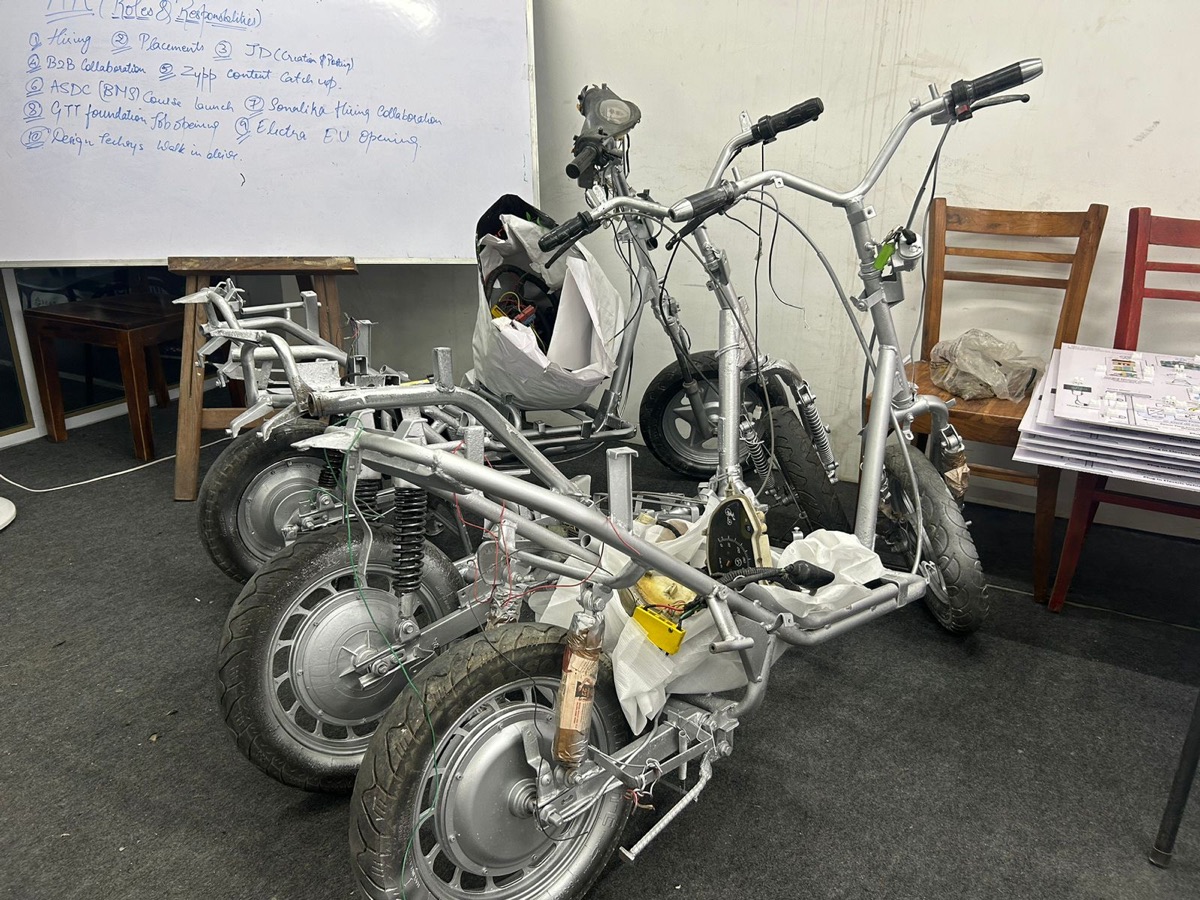
The problem
Small electric quadricycles and city vehicles need a tight turning circle for crowded streets, but poor steering geometry causes tyre scrub, extra wear and heavy steering. Ackermann geometry tries to make both front wheels turn about a common centre. Designing the linkage to approach that, within packaging limits, is a classic and useful exercise.
Objectives
- Define wheelbase, track and target turning radius for an example quadricycle.
- Lay out a rack-and-pinion steering linkage with steering arm angle and rack position as parameters.
- Use a Motion study to measure inner and outer wheel angles through the steering range.
- Tune geometry to reduce Ackermann error and report turning radius and rack travel.
What you need
Tools and toolboxes
- SOLIDWORKS Layout sketch and Blocks — Plan-view layout of kingpins, steering arms, tie rods and rack with blocks for fast trials.
- SOLIDWORKS Assembly with mates — Concentric kingpin and ball-joint pivots and a rack and pinion mechanical mate between pinion and rack.
- SOLIDWORKS Motion Study — A rotary motor on the pinion or linear motor on the rack, with angle plots for each wheel; Basic Motion is enough for kinematics.
- Design Tables — Steering arm angle and rack offset variants.
- Excel — Ideal Ackermann angle calculation, error plots and turning radius.
Software
- SOLIDWORKS 2023 or later
- Excel
Extra parts and data
None beyond the software above.
Key concepts
- Ackermann condition
- For low-speed turning without tyre slip, cot(δo) − cot(δi) = t/L, where δo and δi are outer and inner wheel angles, t the kingpin track and L the wheelbase.
- Ackermann percentage
- How closely the actual inner-to-outer angle difference matches the ideal; 100 per cent is full Ackermann, 0 per cent is parallel steer.
- Steering trapezoid
- The four-bar formed by the axle line, steering arms and tie rods; angling the arms inwards towards the rear axle gives Ackermann effect.
- Turning radius
- The radius of the circle traced by the outer front wheel at full lock, which sets the kerb-to-kerb turning circle.
Step-by-step guide
- 1
Set requirements
Define an example quadricycle with wheelbase 2.0 m, front track 1.2 m, kingpin track 1.1 m and target kerb-to-kerb turning circle of about 8 m. Set a maximum inner wheel angle from tyre and arch clearance, for example 40 degrees, and a rack travel and steering ratio target. Note that low-speed manoeuvring matters most for a city vehicle, which favours close-to-Ackermann geometry.
Checkpoint: A requirements table with dimensions, target turning circle, maximum angle and rack travel.
- 2
Calculate the ideal angles
In Excel, for a range of inner wheel angles from 0 to the maximum, calculate the ideal outer angle from the Ackermann condition. Compute the turning radius at full lock. Also compute the classic starting point for the steering arm angle, where arm lines meet at the centre of the rear axle. These values give a target curve to compare against the linkage.
Checkpoint: An ideal outer-versus-inner angle table and a predicted turning radius at full lock.
- 3
Lay out the linkage
In a Layout sketch in plan view, place kingpin points, steering arms, tie rods and the rack. Make each element a block. Constrain the arm angle and rack offset with dimensions linked to global variables. Drag the rack through its travel and read the wheel angles from angular dimensions. Compare with the ideal curve at a few points. Keep the layout in the top plane of the assembly so the later solid parts can reference it directly.
Checkpoint: A working layout where moving the rack turns both wheels and the angles can be read.
- 4
Tune the layout
Change the steering arm angle and the rack's fore-aft position relative to the axle, and record the angle error at several inner wheel angles. A rack ahead of or behind the axle line changes the effective Ackermann. Aim for small error at low and medium angles where most manoeuvring happens, accepting some error at full lock. Record the best two or three geometries.
Checkpoint: A shortlisted geometry with Ackermann error below an example 1.5 degrees up to 30 degrees inner angle.
- 5
Model the parts
Model uprights or stub axles with kingpins, steering arms, tie rods with ball-joint ends, rack housing, rack and pinion. Use steel from the material library and realistic sizes. Create the pinion and rack with consistent module, or use Toolbox gears if available. Link pivot locations to the layout or check them against it. Give tie rods threaded ends or adjusters so toe can be set on the real vehicle, and note the adjustment range.
Checkpoint: Parts with pivot positions matching the layout, and a pinion and rack of matching module.
- 6
Assemble and add mechanical mates
Fix the chassis plane. Add concentric mates for kingpins and ball joints; use a universal-type pair of concentric mates or a simple concentric for ball joints in a planar analysis. Add a rack and pinion mechanical mate with the correct travel per revolution. Add limit mates to stop the rack at full lock. Check that turning the pinion moves both wheels.
Checkpoint: Rotating the pinion turns both wheels smoothly to full lock with no mate errors.
- 7
Run the Motion study
In a Motion study, add a rotary motor on the pinion that turns it from centre to full left lock over a set time. Basic Motion is sufficient for kinematics. Create plots of each wheel's angle about its kingpin using angular displacement results, or measure angles with sensors. Export to CSV and plot actual outer angle against inner angle with the ideal curve.
Checkpoint: A plot of actual against ideal outer angle across the full steering range.
- 8
Evaluate error and turning circle
Compute Ackermann error and Ackermann percentage at each inner angle. Compute turning radius from the outer wheel angle at full lock and compare with the target. Check rack travel and the overall steering ratio from pinion rotation to average wheel angle. If the turning circle misses the target, consider a larger maximum angle and check clearance. Present the results as a single table so the effect of each geometry change is easy to follow.
Checkpoint: Error curve, Ackermann percentage, turning circle and steering ratio tabulated against targets.
- 9
Check clearances
At full lock in both directions, run Interference Detection between tyres, arches, tie rods and the chassis. Use a tyre envelope with suspension at full bump if you have suspension travel. Add a Collision Detection check while animating if useful. Adjust maximum angle or arch shape if clearance fails. Also check that the tie rod and steering arm never approach a straight-line toggle at full lock, which would make steering heavy or lock up.
Checkpoint: No interference at full lock in either direction with the clearance envelope.
- 10
Drawings and report
Make drawings of the steering arm and tie rod with key dimensions and tolerances on pivot positions. Write up requirements, ideal calculation, layout tuning, motion results, error and turning circle, and clearance checks. Note limitations: kinematics only, no tyre slip angles, no compliance. Suggest a turning-circle test on a prototype. Show the toe adjustment range on the tie rod drawing and specify thread hand for each end.
Checkpoint: Drawings and a report with error curves and turning circle compared with targets.
Testing & validation
- Layout and Motion results agree on wheel angles.
- Ideal Ackermann curve calculated independently in Excel matches the formula.
- Turning circle at full lock compared with target.
- No interference at full lock in either direction.
Expected results
A tuned steering linkage with angle-error curves, Ackermann percentage, turning circle, steering ratio and clearance checks, plus drawings of the main steering parts.
Take it further
- Add suspension travel and plot bump steer.
- Compute steering effort with tyre aligning torque estimates.
- Compare rack ahead of axle and rack behind axle layouts.
- Design an electric power steering motor mount.
Viva and review questions
What is the Ackermann condition?
For slip-free low-speed turning both front wheels must point to a common turn centre on the rear axle line, giving cot(δo) − cot(δi) = t/L.
Why not always use 100 per cent Ackermann?
At higher speeds tyres run at slip angles, and full Ackermann can make the inner tyre work harder. Many vehicles use less than full Ackermann as a compromise.
How did you measure wheel angles in the Motion study?
With angular displacement plots of each upright about its kingpin axis, exported to Excel and compared with the ideal curve.
What limits the turning circle?
The maximum wheel angle, which is limited by tyre clearance to arches and chassis, drive shafts if fitted and rack travel.
Learn it at DIYguru
These DIYguru courses and programmes teach what this project needs.