
Why this happens
A Hall-effect sensor switches when a magnet passes it. Fix a magnet to a spoke and the sensor to the frame, and you get one pulse per wheel revolution. Measuring the time between pulses and multiplying by the wheel's circumference gives speed. It is the same principle many vehicle speed sensors use, built safely as a separate, battery-powered gadget.
What you need
Tools
- Soldering iron and solder
- Measuring tape
- Laptop with the Arduino IDE
- Digital multimeter
Materials
- Arduino Nano or ESP32 board
- Hall-effect switch sensor module
- Spoke magnet
- Small OLED display
- Small power bank or battery holder with a switch
- Weatherproof project box, cable ties and heat-shrink
Before you start
- Do not connect this build to the vehicle's speed sensor, meter or wiring, and do not use it to alter any reading shown on the vehicle's display.
- Keep the magnet, sensor and cables well clear of spokes, brake discs and steering movement.
- Do not read or adjust the display while riding; glance only, as you would at any meter.
Step by step
- 1
Measure the wheel circumference
Mark the tyre and the ground with chalk at the bottom of the wheel, roll the bicycle or vehicle forward one full turn with your weight on it, and mark the ground again. Measure the distance between marks in millimetres. This rolled circumference is more accurate than calculating from the tyre size, because the tyre squashes under load.
- 2
Test the sensor on the bench
Power the board from USB. Wire the Hall module to power, ground and a digital pin that supports interrupts. Upload a simple sketch that lights the onboard LED when the sensor switches. Pass the magnet past the sensor and find the distance and orientation at which it switches reliably; many sensors respond to only one pole of the magnet.
- 3
Write the speed code
Use an interrupt to record the time of each pulse. Ignore pulses that arrive impossibly fast, which removes switch bounce. Speed in km/h is circumference in millimetres divided by the time between pulses in milliseconds, multiplied by 3.6. Count pulses for distance. If no pulse arrives for a few seconds, show zero speed.
Tip: Average the last few pulse intervals for a steadier display.
- 4
Add the display
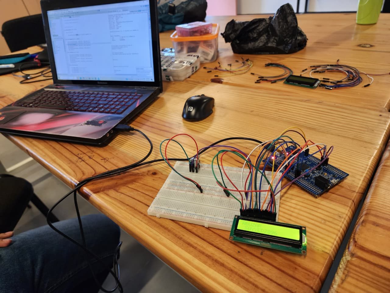
Wire the OLED to the board's I2C pins and show current speed in large digits, with distance and ride time underneath. Keep the layout simple so it can be read at a glance. Update the display a few times a second; updating too often wastes power and makes digits flicker.
- 5
Mount the magnet and sensor
Fit the magnet to a spoke, or to the wheel where it will not touch anything, and the sensor to the fork or frame so the magnet passes within its switching distance. Secure the sensor with cable ties and route its cable away from the brake, wheel and steering. Do not connect anything to the vehicle's own wiring, speed sensor or meter.
- 6
Power and protect the build
Put the board and display in a weatherproof box mounted where you can see it without blocking lights, controls or your view. Power it from its own small power bank or battery holder with a switch, not from the vehicle's battery. Seal cable entries and protect solder joints with heat-shrink against vibration and rain.
- 7
Calibrate on a known distance
Ride or push the bicycle along a measured distance, such as a sports track or a route measured on a map, and compare the distance shown. Adjust the circumference value if needed. Compare speed with a phone GPS app at a steady speed, checked by a passenger or after the ride, never while you are riding.
How to tell it worked
The display shows speed that matches a GPS reference at steady speeds, and distance over a measured route is within a small margin after calibration.
Stop and call a technician if
- The sensor or cable rubs on the wheel or brake, or anything comes loose on a test ride.
- Mounting the sensor would need drilling or removing parts of the vehicle under warranty.
Questions
Why does my speed jump to very high values?
Switch bounce or electrical noise is creating extra pulses. Ignore pulses that are closer together than physically possible and keep the sensor cable short and tied down.
Can I fit this to my electric scooter?
As a separate, battery-powered gadget, yes, if the magnet and sensor can be fixed safely without modifying the vehicle. Never connect it to the scooter's own wiring or speedometer.