
The problem
Most EV control software, from throttle mapping to motor control, is now designed as Simulink models and turned into C code automatically. Students often learn modelling and embedded C separately and never see the link. A throttle-to-PWM chain on a real microcontroller is the smallest complete example of model-based design: model, simulate, generate, deploy and check that the hardware behaves like the model.
Objectives
- Model a throttle-to-PWM map with a dead zone, scaling and rate limiting in Simulink.
- Configure the model for the STM32F103 target and generate C code with Embedded Coder.
- Deploy the code and verify ADC reading and PWM output on the kit.
- Compare on-board results with simulation for the same inputs.
- Read and explain the generated code and its timing.
What you need
Tools and toolboxes
- Simulink — Throttle map, rate limiter and fixed-step model of the control logic.
- Embedded Coder — Generating readable, efficient C code from the model and the code-generation report.
- Embedded Coder Support Package for STMicroelectronics STM32 Processors — Hardware board settings, ADC, PWM and UART peripheral blocks and the build-and-deploy workflow with STM32CubeMX; check the installed version supports the STM32F1 family, and otherwise integrate the generated algorithm code into a STM32CubeIDE project by hand.
- MATLAB Coder — Required by Embedded Coder for code generation.
From the EV Embedded Development Kit
- STM32F103C8T6 microcontroller unit (Arm Cortex-M3)
- Analog potentiometer input
- RGB LEDs and a buzzer
- Motor driver for PWM motor-control experiments
- Serial UART interface
Software
- MATLAB R2023b or later
- Simulink
- STM32CubeMX and STM32CubeIDE
- A serial terminal for UART output
Extra parts and data
- A small brushed DC motor within the motor driver's rating — Only needed if the PWM output is also used to drive a motor; the LED part of the project works with the kit alone.
Key concepts
- Model-based design
- The model is the specification: it is simulated to check behaviour, then the same model generates the code that runs on the target, so design and implementation stay consistent.
- Fixed-step discrete model
- Embedded code runs at fixed rates, so the model uses a fixed-step discrete solver with a sample time equal to the task period, for example 10 ms.
- PWM duty cycle
- The fraction of each PWM period the output is high. Average voltage to an LED or motor is roughly duty × supply voltage.
- ADC scaling
- The STM32F103 ADC is 12-bit, so readings run from 0 to 4095 for 0 to 3.3 V. The model must scale counts to a normalised throttle before mapping.
Step-by-step guide
- 1
Set requirements
Write down what the software must do: read the potentiometer every 10 ms, apply a 5 per cent dead zone at the bottom, map 0 to 100 per cent throttle to 0 to 95 per cent duty, limit the rate of change to 50 per cent per second, and drive the PWM at 1 kHz for the LED (and up to 20 kHz for the motor driver if used). Number each requirement so later tests can refer to it.
Checkpoint: A numbered requirement list that a classmate can test without asking you questions.
- 2
Model the algorithm
Create a model with a fixed-step discrete solver and a 0.01 s step. Use a Gain to convert ADC counts to a 0–1 throttle, a Dead Zone block, a 1-D Lookup Table for the throttle-to-duty map, a Rate Limiter and a Saturation block. Put these in an atomic subsystem called ThrottleMap so it generates as one function. Drive it from a Signal Editor or Repeating Sequence for simulation.
Checkpoint: Simulation with a slow ramp input shows zero output in the dead zone, a linear rise and a capped maximum of 95 per cent.
- 3
Test the model in simulation
Create three test inputs: a slow ramp, a sudden step from 0 to 100 per cent and a noisy constant. Run each and inspect results in the Simulation Data Inspector. Check that the step response climbs at the rate limit and reaches full duty in about 1.9 s, and that noise is passed through but bounded. Save expected outputs to compare against hardware later.
Checkpoint: The step test reaches 95 per cent duty after about 1.9 s, matching the rate-limit requirement.
- 4
Configure the hardware target
Install the STM32 support package from the Add-On Explorer and follow its setup to link STM32CubeMX. In the model's Hardware Implementation settings, choose the STM32 board or processor family that matches the STM32F103C8T6 and point to an STM32CubeMX project (.ioc) where you enable ADC1 on the potentiometer pin, a timer channel for PWM on an LED pin and USART for debug. Set the HCLK to 72 MHz.
Checkpoint: The model's hardware settings show the STM32 target and the .ioc file opens with ADC, timer PWM and USART enabled.
- 5
Add peripheral blocks
Make a top-level hardware model that places the ADC Read block from the support package before ThrottleMap and the PWM Output block after it. Keep ThrottleMap identical to the tested version, ideally as a referenced model, so the logic you simulated is exactly the logic you deploy. Add a UART block that sends the ADC count and duty every 100 ms for logging.
Checkpoint: The hardware model updates without errors (Ctrl+D) and ThrottleMap is referenced, not copied.
- 6
Generate and read the code
Use Embedded Coder's Quick Start or set the system target file to ert.tlc and build. Open the code-generation report and find the ThrottleMap step function: identify the dead zone, lookup interpolation and rate limiter in the C code. Check the static memory and the data types. Since the F103 has no FPU, note any single-precision operations; they work but are emulated in software.
Checkpoint: You can point to each block's code in the report and state the size of the generated step function's code and data.
- 7
Deploy and observe
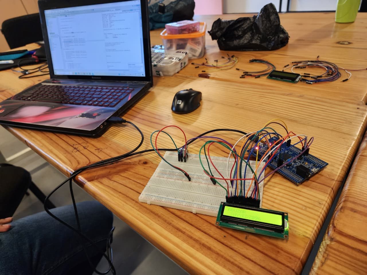
Build, deploy and start the application on the kit using the support package's deploy command (or by importing the generated code into STM32CubeIDE). Enable the potentiometer, LED and UART DIP switches as required. Turn the potentiometer slowly and watch the LED brightness change. Log the UART stream to a CSV file with a serial terminal or a MATLAB serialport script.
Checkpoint: The LED is off near the bottom of the potentiometer travel and brightens smoothly towards the top.
- 8
Compare hardware with simulation
Turn the potentiometer quickly from minimum to maximum and capture the logged ADC and duty values. Feed the logged ADC sequence back into the ThrottleMap model in simulation and compare the simulated duty with the logged duty. Plot both. They should match closely, since the same code runs in both, apart from timing jitter in logging. If the traces differ by more than this, check that the model's sample time matches the timer configuration and that the ADC scaling in the model matches the actual reference voltage.
Checkpoint: Simulated and logged duty overlap, with a maximum difference below 1 per cent duty.
- 9
Measure timing
Add a GPIO toggle at the start and end of the step function (or use the support package's profiling options, if available) and measure execution time with an oscilloscope or logic analyser if one is available, or with the DWT cycle counter reported over UART. Compare with the 10 ms period to find the CPU load. Check that the PWM frequency is what you configured.
Checkpoint: Measured step-function execution time and CPU load as a percentage of the 10 ms period.
- 10
Drive the motor driver (optional) and report
If a small brushed DC motor is available, route the PWM to the motor driver input at a higher frequency, keep the rate limiter, and observe smooth acceleration. Write the report: requirements, model, simulation tests, target configuration, generated code walkthrough, hardware test against simulation and timing. Keep the motor small and within the driver's rating; nothing in this project needs mains or high-voltage power.
Checkpoint: A report that traces each requirement to a simulation test and a hardware result.
Testing & validation
- Simulation tests for dead zone, mapping, rate limit and saturation.
- Hardware duty compared with simulated duty for the same logged ADC input.
- PWM frequency and duty measured or verified on the target.
- Execution time and CPU load of the step function.
Expected results
A working Simulink-to-STM32 chain on the DIYguru kit: a tested throttle-to-PWM model, generated C code running on the STM32F103, and evidence that hardware behaviour matches simulation.
Take it further
- Convert the model to fixed-point and compare code size and execution time.
- Add a Stateflow mode chart for park, drive and limp modes.
- Send the throttle value on the kit's CAN bus.
- Run the same model as processor-in-the-loop to compare outputs automatically.
Viva and review questions
Why did you put the algorithm in a referenced model?
So that the exact logic tested in simulation is the logic deployed; the hardware model only adds peripheral blocks around it.
Why a fixed-step discrete solver?
The code runs as a periodic task on the microcontroller, so the model must use the same fixed sample time; variable-step solvers cannot generate embedded code.
What happens to floating-point code on the STM32F103?
It still runs, but the Cortex-M3 has no FPU, so float operations are done in software and take many more cycles than integer ones.
Learn it at DIYguru
These DIYguru courses and programmes teach what this project needs.