
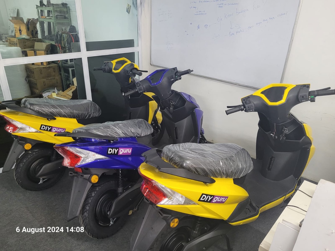
The problem
Electric two-wheelers are very sensitive to mass and cost, and their battery, motor and gearing are often chosen one after another by different teams. Because the components interact, sequential design can leave value on the table. Co-design optimises plant and control together, but it raises questions about formulation, model fidelity and computational cost that suit doctoral research.
Objectives
- Formulate a co-design problem with physical, control and performance variables and constraints.
- Build scalable component models (cell-based pack, scalable motor map, gear ratio, regen strategy).
- Implement sequential design as a baseline.
- Solve the co-design problem with nested and simultaneous strategies and compare.
- Quantify the benefit of co-design and its robustness to uncertainty and drive cycle.
What you need
Tools and toolboxes
- MATLAB — Formulation, scaling laws, optimiser wrappers and analysis.
- Simulink — Vehicle and powertrain models used inside the objective function.
- Global Optimization Toolbox — ga, gamultiobj or surrogateopt for the outer design loop with mixed integer variables.
- Optimization Toolbox — fmincon for the inner control-parameter optimisation in the nested formulation.
- Parallel Computing Toolbox (optional) — Parallel evaluation of candidates to keep run times manageable.
Software
- MATLAB R2023b or later
- Simulink
- Published cell datasheets and a reference two-wheeler motor map
- CSV drive cycles (IDC, a logged city cycle)
Extra parts and data
None beyond the software above.
Key concepts
- Co-design
- Optimising physical design variables and controller parameters together, so the plant is chosen knowing how it will be controlled.
- Nested versus simultaneous formulation
- Nested: for each candidate plant, solve the control problem optimally inside. Simultaneous: treat plant and control variables in one optimisation. Nested is cleaner; simultaneous is often cheaper.
- Sequential design baseline
- Choose the motor from performance targets, then the ratio, then the battery for range, then tune control. Comparing with this shows what co-design actually adds.
- Robust design
- Optimising expected or worst-case performance over uncertain parameters and drive cycles, so the design does not fail when conditions change.
Step-by-step guide
- 1
Formulate the problem
For an example 120 kg scooter with a rider, define plant variables (series and parallel cells, motor torque scale, gear ratio) and control variables (regen torque limit as a function of speed, a torque-command shaping parameter). Objectives: minimise a cost proxy and maximise range; constraints: top speed, 0–40 km/h time, gradeability, peak C-rate and motor continuous rating on a hill test. Write it in standard form with all assumptions listed.
Checkpoint: A formal problem statement with variables, bounds, objectives, constraints and assumptions.
- 2
Build scalable component models
Reuse a cell-based pack model returning energy, mass, resistance and power limit; a scalable motor model with mass and inertia scaling and a scaled efficiency map; a gear model with ratio-dependent mass; and a simple thermal check for continuous rating. Document each scaling law and its range of validity, and compare scaled outputs with any published data available. Write unit tests for each component function so later edits cannot break them.
Checkpoint: Component model outputs for three reference designs, with each scaling law plotted over its valid range.
- 3
Build the evaluation model
Build a forward-facing Simulink model of the scooter using the component models, a driver PI controller and the parametrised regen and torque-shaping logic. Wrap it in evaluate(plant, control) that runs IDC and a logged city cycle plus performance tests and returns objectives and constraints. Use fixed-step ode4 and confirm step-size independence. Log every evaluation with its inputs and outputs to a results file, which allows restarts and later analysis without repeating simulations.
Checkpoint: One evaluation completes in seconds and returns all objectives and constraints; results change by less than 1 per cent with a halved step.
- 4
Implement sequential design
Follow a typical industrial sequence: size the motor from performance targets, choose the ratio for top speed, size the battery for range with a margin, then tune regen and torque shaping with fmincon on energy. Record the resulting design and its objectives as the baseline. Document each decision and the target that drove it, mirroring how a real team would hand over between motor, gearing and battery work. This makes the baseline fair and reproducible.
Checkpoint: A sequential baseline design that meets every constraint, with its cost proxy and range recorded.
- 5
Solve the nested co-design
Use an outer genetic or surrogate search (ga, gamultiobj or surrogateopt) over plant variables, and inside each evaluation run fmincon over control variables to minimise energy subject to drivability limits. Cache inner results and use parallel evaluation if available. Track the number of simulations used. Warm-start each inner optimisation from the best control parameters of a nearby plant design to cut inner iterations, and check that warm starting does not change the inner optimum.
Checkpoint: A nested co-design Pareto front or single-objective optimum with the number of simulations reported.
- 6
Solve the simultaneous co-design
Combine plant and control variables in one gamultiobj or surrogateopt problem with the same constraints. Compare the resulting front with the nested one using hypervolume, and compare computational cost. Explain any differences with reference to the coupling between plant and control variables. Run each formulation with several random seeds and report the spread of hypervolume, so that a lucky single run does not decide the comparison. Use the same evaluation budget for both formulations.
Checkpoint: Hypervolume and simulation count for both formulations, with the fronts plotted together.
- 7
Compare with the baseline
Locate the sequential baseline on the co-design fronts and find co-design solutions that dominate it. Quantify improvements in cost proxy at equal range, or range at equal cost. Explain physically why the co-designed solution differs (for example a slightly smaller motor with a shorter ratio and more aggressive regen). Also check whether the improvement survives small changes to the targets, since a large gain at one exact target can disappear when targets move.
Checkpoint: A dominated-baseline plot and a table of improvements with physical explanations.
- 8
Robustness to uncertainty and cycles
Re-evaluate the best designs with uncertain mass, Crr, cell capacity and motor efficiency (Monte Carlo) and on cycles not used in the optimisation. Then reformulate with an expected-value or worst-case objective over a set of cycles and compare the robust design with the nominal one. Report constraint violation probability as well as mean performance, since a design that fails a gradeability or thermal constraint occasionally may be unacceptable in a product.
Checkpoint: Distributions of range and constraint margins for nominal and robust designs, and their performance on unseen cycles.
- 9
Model fidelity check
Take two or three final designs and evaluate them with a higher-fidelity model (for example an ECM battery with voltage sag and a motor map not derived from scaling) to check that the ranking holds. If it does not, explain which simplification causes the change. If the ranking changes, consider re-running the optimisation with the higher-fidelity model on a reduced design space around the candidates, and report how much the answer moves.
Checkpoint: A ranking comparison between the optimisation model and the higher-fidelity model.
- 10
Write up
Present the formulation, component models, verification, baseline, both co-design formulations, comparisons, robustness and fidelity checks. Release code and models. State the main limits: example parameters, approximate scaling laws, a cost proxy rather than costs, and simulated rather than measured results. Include a section on computational cost: simulations used, wall-clock time and how the method would scale to more design variables, a larger vehicle class or several drive cycles.
Checkpoint: A thesis chapter with reproducible results quantifying the benefit of co-design over sequential design.
Testing & validation
- Component scaling laws compared against reference data within stated ranges.
- Evaluation results independent of solver step size.
- Co-design results meet every constraint.
- Rankings hold under a higher-fidelity model.
- Robust designs tested on unseen cycles.
Expected results
A co-design framework for an example electric two-wheeler with nested and simultaneous solutions, a quantified comparison with sequential design, robustness analysis and a fidelity check of the final rankings.
Research angle for your PhD
Research questions: how much does co-design improve cost and range over sequential design for electric two-wheelers, which couplings cause the gain, and which formulation (nested or simultaneous) gives the best result per simulation? Baselines: a documented sequential design and a single-objective optimisation. Metrics: hypervolume, improvement at equal range or cost, simulation count, and robustness under uncertainty and unseen cycles. A publishable result needs a clear formulation, validated scaling laws, fair baselines and released models, and ideally a fidelity check that shows the conclusions survive a more detailed model.
Take it further
- Add battery ageing to the objective for total cost over life.
- Include cell chemistry selection as a categorical variable.
- Use dynamic programming for the inner control problem.
- Extend to a three-wheeler fleet with route-specific cycles.
Viva and review questions
What is the difference between co-design and sequential design?
Sequential design fixes each component in turn using targets, then tunes control at the end. Co-design chooses plant and control variables together so their interactions are exploited.
Why compare nested and simultaneous formulations?
Nested gives an optimal controller for every plant but costs many more simulations; simultaneous is cheaper but harder to converge. The comparison shows the practical trade-off.
How do you know the gain is not an artefact of the simplified model?
I evaluated the final designs with a higher-fidelity model and checked that the ranking and most of the improvement remained.
Why include robustness?
An optimum on one cycle with exact parameters can be fragile. Testing with uncertainty and unseen cycles shows whether the design remains feasible and good in practice.
Learn it at DIYguru
These DIYguru courses and programmes teach what this project needs.
- CourseCertification Course in MATLAB-SIMULINK, QSS & Advisor Toolbox for EV Design
- CourseAdvanced Certification Course in EV Design & Simulation using MATLAB
- ProgrammeAdvanced Nanodegree Certification Program in EV Engineering, Design, Simulations, and Analysis
- ProgrammePCP in EV Electrical Design & Simulation