
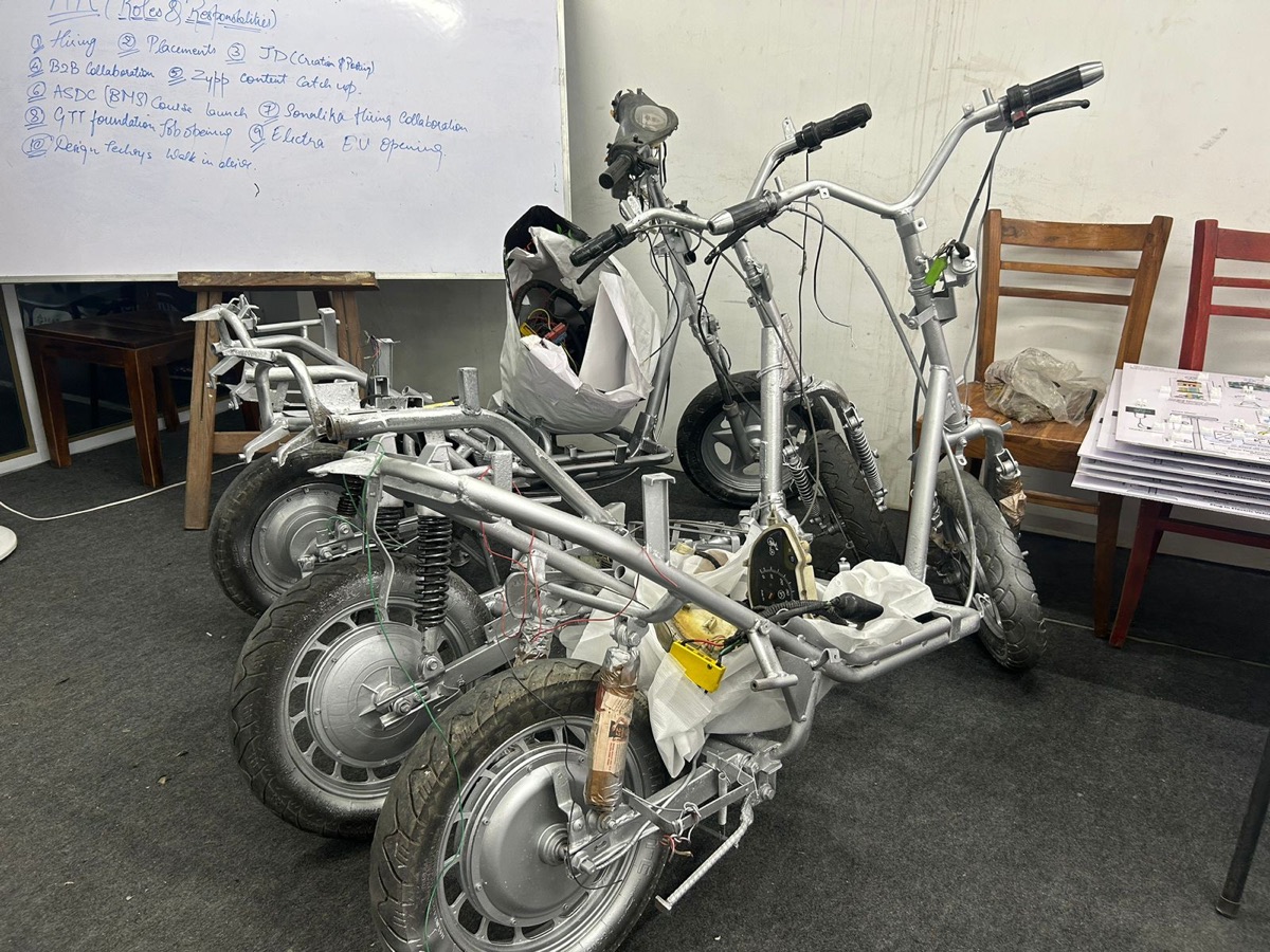
The problem
The frame is the backbone of an electric scooter: it carries the rider, holds a heavy battery low in the chassis and takes braking and bump loads from the fork and rear suspension. Student designs are often drawn around a copied outline and never checked. A frame built from a packaging layout and a structural check is lighter, easier to fabricate and defensible in a review.
Objectives
- Build a 2-D and 3-D packaging layout for rider, battery, hub motor, wheels and steering head.
- Model the frame with Weldments structural members, trims, gussets and end caps.
- Generate a cut list with lengths, angles and mass for fabrication.
- Check the frame under example vertical, bump and braking load cases with a factor of safety target.
- Produce a fabrication drawing with a weldment cut list table and weld symbols.
What you need
Tools and toolboxes
- SOLIDWORKS Part (3D Sketch, Weldments) — Frame skeleton in 3D sketches, Structural Member with standard and custom tube profiles, Trim/Extend, Gusset, End Cap and Weld Bead.
- SOLIDWORKS Assembly — Packaging check with simplified battery, motor, wheel and rider blocks, plus Interference Detection.
- Mass Properties — Frame mass and the centre of gravity of the loaded vehicle.
- SOLIDWORKS Simulation (Static) — Beam-element static study of the frame under rider, bump and braking loads; Simulation Standard is enough.
- SOLIDWORKS Drawings — Weldment cut list table, balloons, weld symbols and general tolerances to ISO 2768.
Software
- SOLIDWORKS 2023 or later
- SOLIDWORKS Simulation (Standard or higher)
- Excel for load and mass tables
Extra parts and data
- A reference scooter to measure (optional) — Wheelbase, seat height, steering head angle and battery bay size from a real vehicle give a realistic starting layout.
Key concepts
- Weldment structural member
- A feature that sweeps a 2-D profile, such as a round or square tube, along sketch segments. Each member becomes a body in the cut list with its length and end angles.
- Cut list
- An automatically maintained list of weldment bodies grouped by profile and length. It feeds the fabrication drawing and the mass estimate.
- Beam elements
- Simulation can mesh weldment members as beams with joints at their ends. This is fast and suits a tube frame, but it does not show local stress at welds and gussets.
- Factor of safety
- Material yield strength divided by the peak von Mises stress. A frame design target of, for example, 2 under a bump load leaves margin for fatigue and weld quality.
Step-by-step guide
- 1
Set requirements and an example load
Write a one-page requirement sheet for an example city scooter: 120 kg rider plus payload, 30 kg battery, 12-inch wheels, wheelbase about 1300 mm and a seat height near 760 mm. Define three load cases: static riding weight, a vertical bump at 3 g on the rear axle and a front braking case with 0.8 g deceleration. Choose an example material such as ERW mild steel tube or AISI 4130 and record its yield strength from the SOLIDWORKS material library.
Checkpoint: A requirement table with mass, geometry, load cases and a target factor of safety of at least 2 for the bump case.
- 2
Build the packaging layout
In a new part, sketch a side-view layout on the Right Plane: ground line, wheel circles, steering head axis with an example 25° rake, seat height point, footboard and the battery bay. Dimension these with driving dimensions and link key values to Global Variables (wheelbase, rake, seat height) so the layout updates when you change one number. Insert simplified battery and rider blocks into an assembly to see the space they take.
Checkpoint: Changing the wheelbase Global Variable rebuilds the whole layout without sketch errors.
- 3
Draw the frame skeleton
Create a 3D Sketch for the main down tubes, steering head, seat rails and cross members, using the layout sketch as reference. Add Coincident, Symmetric and Along Z relations so left and right rails mirror about the centre plane. Keep every node at a real tube intersection and avoid tiny segments, since each segment becomes a member. Fully define the sketch so that it shows black.
Checkpoint: The 3D Sketch is fully defined and mirrors correctly when the frame width dimension is changed.
- 4
Add structural members
Use Weldments > Structural Member to place tubes on the skeleton, for example 25.4 × 1.6 mm round tube for the main rails and 20 × 20 × 1.5 mm square tube for cross members. Create separate groups so corner treatment works correctly, and use Trim/Extend to cope tube ends. Add a steering head tube as a separate extruded body and a seat-rail end cap where tubes are open.
Checkpoint: All members are created without overlapping bodies, and the cut list shows each tube with sensible lengths and angles.
- 5
Add gussets, brackets and welds
Place Gussets at the steering head and swingarm pivot where bending is highest. Model the battery mounting brackets and motor or swingarm pivot plates as sheet bodies or extrusions merged into the weldment. Add Weld Bead features or cosmetic weld beads at critical joints so they appear on the drawing. Assign the frame material and check the cut-list properties, including mass per item.
Checkpoint: Mass Properties gives a frame mass in a believable range for the example design, for example 8–14 kg for steel.
- 6
Check packaging and interference
Insert the frame into the vehicle assembly with the battery, hub motor, wheels, fork and a simple rider manikin made of blocks. Run Interference Detection and fix clashes between the battery and cross members. Measure ground clearance and steering lock clearance with the Measure tool. Use Mass Properties on the assembly to find the loaded centre of gravity height and its position between the axles.
Checkpoint: Interference Detection reports no unintended interferences and the centre of gravity sits low and roughly mid-wheelbase.
- 7
Set up the static study
Start a Static study. Let Simulation treat the members as beams and use Edit Joints to confirm joints are found at every node. Fix the rear axle mount with a Fixed Hinge and the steering head with a Roller/Slider so the frame is not over-constrained. Apply the rider load as distributed forces on the seat rails and the battery as a force or Remote Mass on its brackets. Add Gravity for frame self-weight.
Checkpoint: The study runs, the deformed shape looks physically sensible and reaction forces sum to the applied loads.
- 8
Run the three load cases
Duplicate the study for bump (3 g vertical) and braking (0.8 g longitudinal at the contact patch, carried into the frame through the steering head). Plot Upper Bound Axial and Bending stress and resultant displacement for each. Use a Factor of Safety plot based on yield. Check the highest stress member by hand using a simple beam formula, M·c/I, to confirm Simulation is in the right order of magnitude.
Checkpoint: Minimum factor of safety is at least 2 in the bump case and the hand calculation agrees with the beam result within about 15 per cent.
- 9
Iterate the design
If a member fails the target, change its wall thickness or profile in the Structural Member feature, add a gusset or move a cross member to shorten the bending span. If the factor of safety is very high everywhere, reduce wall thickness to save mass. Record each iteration in a table with mass, peak stress and peak deflection so the final choice is clearly justified, not guessed.
Checkpoint: An iteration table showing at least two design changes and the mass and factor of safety for each.
- 10
Make the drawing and report
Create a drawing with the frame in three views and an isometric, a Weldment Cut List table with item numbers, lengths and angles, balloons and weld symbols. Add general tolerances to ISO 2768-m in the title block. In the report, include the layout, load cases, stress and displacement plots, the hand check and the iteration table. State that beam results do not capture local weld stresses and that a physical load test is needed before use.
Checkpoint: A drawing that a fabricator could cut and weld from, and a report with all three load cases and their factor of safety.
Testing & validation
- Reaction forces in each study balance the applied loads.
- Hand calculation of the most loaded member agrees with the beam result within about 15 per cent.
- Factor of safety meets the stated target in every load case.
- Interference Detection passes for the packaged assembly.
- Cut list lengths match the drawing and the frame mass from Mass Properties.
Expected results
A packaged, fully defined SOLIDWORKS weldment frame for an example electric scooter with a cut list, three verified load cases, an iteration record and a fabrication drawing.
Take it further
- Model the welded joints as solid bodies and run a local stress study at the steering head.
- Add a Frequency study to check frame modes against motor and road excitation.
- Compare round and square tube frames for mass and stiffness.
- Fabricate a scaled frame and compare measured deflection with Simulation.
Viva and review questions
Why model the frame as beams rather than solids?
Beams are fast and give axial and bending stress in each tube, which is what governs a tube frame. They do not capture local stresses at welds, so critical joints should be checked separately with solid or shell models.
How did you avoid over-constraining the model?
I fixed the rear axle with a hinge and supported the steering head with a roller, so the frame could deflect naturally. Fixing both ends rigidly would make it look stiffer and shift stresses.
Why did you use Global Variables for the layout?
Wheelbase, rake and seat height drive many sketch dimensions. Linking them to Global Variables lets me change one value and rebuild the layout and frame consistently.
How do you know the stress values are right?
Reaction forces balanced the loads, and a hand bending calculation on the most loaded tube agreed with the beam result. A physical load test would still be needed before production.
Learn it at DIYguru
These DIYguru courses and programmes teach what this project needs.
- CourseCertification Course in 2W EV Design & Modeling with SOLIDWORKS
- CourseCertification Course in 2W & 4W EV Design & Modeling with SOLIDWORKS
- ProgrammeAdvanced Nanodegree Certification Program in EV Engineering, Automotive Design, Development, & Dynamic Analysis
- ProgrammePCP in EV Automotive Design & Simulation