
The problem
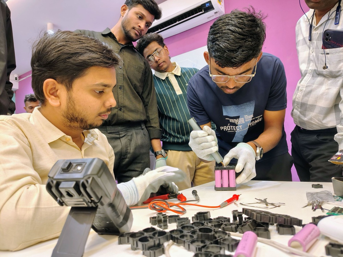
Cell-to-pack designs remove modules and bond cells directly into the pack, which raises energy density and can make the pack part of the vehicle structure. The cost is serviceability: bonded cells are hard to replace, and repair or recycling becomes difficult. Engineers need ways to quantify structural benefit against service penalties early in design.
Objectives
- Model a module-based baseline and a cell-to-pack concept of the same pack.
- Develop equivalent orthotropic properties for a bonded cell block from a detailed unit cell.
- Compare torsional and bending stiffness of body plus pack for both concepts.
- Identify load paths through cells and adhesive and stress in the adhesive layer.
- Define and compare serviceability metrics and propose design features that improve repairability.
What you need
Tools and toolboxes
- SOLIDWORKS Part and Assembly — Baseline module pack, cell-to-pack concept, unit cell model and a simplified body floor.
- SOLIDWORKS Simulation (Static) — Unit cell homogenisation runs and full stiffness studies with linear elastic orthotropic materials; Simulation Standard is enough.
- SOLIDWORKS Simulation (Frequency, optional) — Global mode comparison; requires Simulation Professional or Premium.
- SOLIDWORKS Composer or exploded views — Service sequence illustrations and disassembly step counting.
- MATLAB or Excel — Homogenised property calculation, stiffness metrics and serviceability scoring.
Software
- SOLIDWORKS 2023 or later
- SOLIDWORKS Simulation (Standard; Professional for Frequency)
- MATLAB or Excel
Extra parts and data
- Structural adhesive and potting material data — Modulus, shear strength and temperature behaviour from datasheets are required for the bonded layer.
- Cell mechanical data — Effective cell stiffness depends on cell construction; published compression test data should be used where available.
Key concepts
- Cell-to-pack
- A pack design where cells are mounted directly in the pack structure without separate modules, saving mass and volume.
- Homogenisation
- Replacing a detailed repeating structure, such as cells in adhesive, with a uniform material that has the same overall stiffness, found from unit cell analyses.
- Orthotropic material
- A material with different stiffness in three perpendicular directions. A bonded cell block is stiffer along the cell axis than across it.
- Serviceability
- How easily a pack can be inspected, repaired or disassembled. Metrics include steps, time and parts destroyed to replace one cell group.
Step-by-step guide
- 1
Define the study and metrics
Define an example EV floor and pack: a 60 kWh pack between sills with cylindrical cells. State research questions: how much stiffness does a bonded cell-to-pack design add to the body, where do loads travel and what does it cost in serviceability? Define structural metrics (torsional and bending stiffness, adhesive stress) and serviceability metrics (steps, estimated time, parts destroyed to replace a cell group).
Checkpoint: A study plan with research questions and defined metrics for both structure and service.
- 2
Model the baseline module pack
Model a conventional pack: tray, lid, cross members and modules bolted in, each module a block with correct mass and equivalent stiffness. Bolt the pack to a simplified body floor with sills and cross members modelled as shells. Check mass and centre of gravity with Mass Properties. This baseline sets reference values for stiffness and serviceability. Use the same tray outline and body floor as the concept so differences come from the pack structure.
Checkpoint: Baseline assembly with recorded mass and centre of gravity, passing Interference Detection.
- 3
Model the cell-to-pack concept
Model the concept: cells arranged directly in the tray, bonded with adhesive to the tray floor and the lid, with a structural lid acting as the cabin floor. Model a representative unit cell in detail, containing a few cells, adhesive layers and tray and lid sections, for homogenisation. Keep the full concept as a block of homogenised material between tray and lid.
Checkpoint: A detailed unit cell model and a full concept model with a homogenised core.
- 4
Homogenise the cell block
Run Static studies on the unit cell under unit strains or loads in each direction and in shear, with periodic-like boundary conditions approximated by symmetry and coupling. Compute effective moduli and shear moduli from reaction forces and displacements in MATLAB or Excel. Create a linear elastic orthotropic custom material with these properties and set its axes to the cell orientation.
Checkpoint: A set of effective orthotropic properties, with the unit cell and homogenised block giving the same stiffness within about 5 per cent in a check load case.
- 5
Compare global stiffness
For baseline and concept, run torsion and bending studies of the body floor with the pack installed, using the same supports and loads. Compute torsional stiffness in N·m per degree and bending stiffness in N per mm. Also run the body without a pack to see how much each pack contributes. Check mesh convergence on global stiffness. Use identical mesh controls for both packs.
Checkpoint: A table of stiffness for body only, body plus baseline and body plus concept, with mesh checks.
- 6
Trace load paths
Plot stress in the lid, tray and homogenised core under torsion and bending to see how much load passes through the cells. Use the global results to drive a sub-model of the unit cell at the most loaded location, and check adhesive shear stress and cell axial stress. Compare adhesive stress with its datasheet strength with a margin. Check that the sub-model boundary displacements come from the global model.
Checkpoint: Load path plots and adhesive stress margins at the most loaded location.
- 7
Check sensitivity to adhesive and cell stiffness
Vary adhesive modulus and effective cell stiffness across the ranges found in datasheets and literature. Repeat homogenisation and global stiffness runs. Plot how stiffness contribution and adhesive stress change. This shows whether conclusions survive uncertainty in material data, which is large for cells. Use at least three levels for each property. Present the results as bands rather than single lines so uncertainty is visible. Note which property drives the result most, since that is where test data is most needed.
Checkpoint: Sensitivity plots showing the range of stiffness contribution and adhesive stress.
- 8
Analyse serviceability
For both designs, define the sequence to replace one failed cell group: remove pack, open lid, access and remove the group, reassemble and reseal. Count steps, tools, fasteners, destroyed parts and an estimated time from standard assembly time tables or your own timed trials on a mock-up. Use exploded views or SOLIDWORKS Composer to document each sequence. Mark destroyed or replaced parts clearly.
Checkpoint: A service sequence for both designs with step counts and estimated times.
- 9
Propose service-friendly features
Design one or two features that improve concept serviceability: segmented bonded blocks that can be removed as units, debond-on-demand adhesive zones or bolted lid sections over each block. Re-run stiffness studies with these changes and repeat the service sequence analysis. Measure what stiffness is lost for each service gain. Keep the feature changes within the same pack envelope and energy capacity so comparisons are fair. Record any change in cell count caused by the feature.
Checkpoint: A trade-off table of stiffness lost against service time saved for each feature.
- 10
Discuss safety and recycling
Discuss effects on thermal propagation, crash load transfer into cells and end-of-life recycling. Note that loading cells structurally raises questions about cell damage under crash and fatigue, which need test data. Reference current battery safety standards such as AIS-038 Rev 2 for M and N categories generally, and check their current text for structural and propagation requirements. Mention how disassembly affects recycling yield.
Checkpoint: A discussion section linking structural results with safety and recycling issues.
- 11
Write up for publication
Report the method, homogenisation verification, global stiffness results, load paths, sensitivity, serviceability metrics and trade-offs, with a clear statement of assumptions. Present a design map showing stiffness contribution against service time for all variants. Provide models and scripts for reproducibility. State clearly which results come from verified homogenisation and which from assumptions. Discuss how the design map could guide a team choosing between module-based and cell-to-pack designs for a given vehicle use. List future tests that would reduce the largest uncertainties.
Checkpoint: A paper-style report with a design map and reproducible models and scripts.
Testing & validation
- Homogenised block matches unit cell stiffness within about 5 per cent.
- Mesh convergence on global stiffness.
- Same supports and loads for all designs.
- Sensitivity to uncertain cell and adhesive properties reported.
- Service sequences documented step by step.
Expected results
A quantified comparison of module-based and cell-to-pack structural battery concepts for an example EV, with homogenised cell-block properties, stiffness contributions, adhesive stress margins, sensitivity to material data and a serviceability trade-off map.
Research angle for your PhD
The research question is how much body stiffness a cell-to-pack structural battery contributes, how sensitive that is to uncertain cell and adhesive properties, and what serviceability it costs. A homogenisation method verified against detailed unit cells, a sensitivity study and a quantified stiffness-versus-service design map would be a clear contribution, especially with physical stiffness data from a bonded cell block.
Take it further
- Measure compression and shear stiffness of a small bonded cell block in a test machine and update the homogenised properties.
- Add a Frequency study of the body with each pack.
- Study fatigue of the adhesive layer under road-load cycles.
Viva and review questions
Why homogenise the cell block?
Modelling thousands of cells and adhesive layers in a full body model is impractical. A homogenised orthotropic material with the same stiffness as the unit cell captures global behaviour efficiently.
How did you check the homogenised properties?
By applying the same load to the detailed unit cell and the homogenised block and confirming stiffness agreed within about 5 per cent.
What is the main drawback of cell-to-pack?
Serviceability. Bonded cells are hard to remove, so repair often means replacing large parts of the pack. I quantified this with service sequence metrics.
How sure are you of the stiffness contribution?
It depends strongly on effective cell and adhesive stiffness, which are uncertain, so I reported a range from a sensitivity study rather than a single number.
Learn it at DIYguru
These DIYguru courses and programmes teach what this project needs.
- CourseCertification Course in 2W & 4W EV Design & Modeling with SOLIDWORKS
- CourseCertification Course in 2W EV Design & Modeling with SOLIDWORKS
- ProgrammeAdvanced Nanodegree Certification Program in Battery and BMS Design, Analysis, & Simulation
- ProgrammeAdvanced Nanodegree Certification Program in EV Engineering, Automotive Design, Development, & Dynamic Analysis