
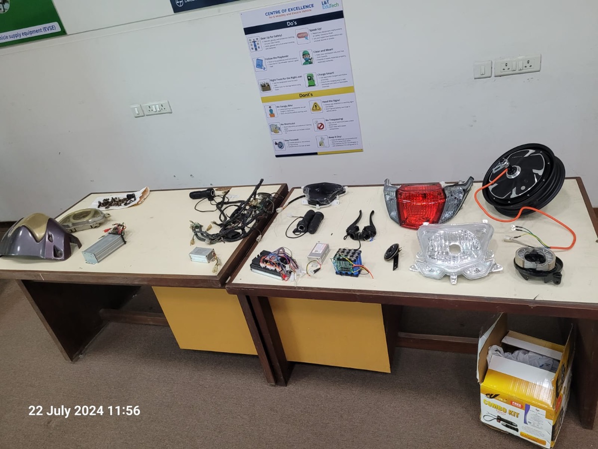
The problem
In a real EV programme the CAD assembly is the single source for the BOM, costing, purchasing and the assembly line. Students often build assemblies that look right but have missing mates, duplicate parts, no part numbers and unusable drawings. Structuring a full vehicle assembly properly is basic preparation for work in a design or manufacturing team.
Objectives
- Structure an example scooter into sub-assemblies that match how it is built.
- Mate parts robustly, use Toolbox fasteners and add custom properties for part number, material and supplier.
- Check interferences, mass and centre of gravity.
- Create an indented BOM, exploded views with balloons and assembly drawings.
- Write assembly instructions, optionally as an interactive Composer file.
What you need
Tools and toolboxes
- SOLIDWORKS Assembly — Sub-assemblies, standard and advanced mates, Mate Controller or configurations for steering angle.
- SOLIDWORKS Toolbox — Standard bolts, nuts and washers with correct sizes and part numbers.
- Custom Properties and Property Tab Builder — Consistent part number, description, material, supplier and make/buy fields for the BOM.
- Interference Detection and Mass Properties — Clash checks and overall mass and centre of gravity of the vehicle.
- SOLIDWORKS Drawings — Exploded views, Explode Line Sketch, Bill of Materials table and Auto Balloon.
- SOLIDWORKS Composer (optional) — Interactive assembly instructions and illustrations; it is a separate product.
Software
- SOLIDWORKS 2023 or later
- SOLIDWORKS Composer (optional)
- Excel for the BOM export
Extra parts and data
- A reference scooter or component dimensions — Measured or published envelope dimensions make the assembly realistic.
Key concepts
- Indented BOM
- A bill of materials that shows sub-assemblies and the parts inside them, matching the build order and how parts are purchased.
- Make/buy
- A property that marks whether a part is manufactured in-house or bought, which changes how it is drawn and costed.
- Fully defined assembly
- Every component is constrained so it cannot move unintentionally, except deliberate degrees of freedom such as steering and wheel rotation.
- Exploded view
- A view with components moved apart along assembly directions so each part and its order of assembly can be seen and ballooned.
Step-by-step guide
- 1
Plan the product structure
Write a product tree for an example scooter: frame, front suspension and steering, rear swing arm with hub motor, battery pack, controller box, body panels, seat and storage, lighting, and electrical harness placeholders. Decide which items are bought (motor, tyres, shock absorbers, fasteners) and which are made. Choose a part numbering scheme, for example a prefix by sub-assembly plus a serial number. This tree becomes the assembly structure.
Checkpoint: A written product tree with about 8 to 10 sub-assemblies and a numbering rule.
- 2
Create a layout and skeleton
Make a skeleton part or a layout sketch in the top assembly with key points: wheel centres, wheelbase (an example 1300 mm), steering axis angle, seat height and battery envelope. Reference sub-assembly positions to the skeleton so changing the wheelbase moves the rear sub-assembly. Keep external references controlled and named, and lock them once the layout is final to avoid slow rebuilds.
Checkpoint: Changing the wheelbase in the skeleton moves the rear sub-assembly correctly with no mate errors.
- 3
Build the sub-assemblies
Model or import each sub-assembly. Use simple geometry for bought parts such as the motor and shocks, based on measured or published envelopes, and detailed geometry for made parts. Mate with Coincident, Concentric and Distance mates, using Width mates for centring and Hinge mates for pivots. Leave steering rotation and wheel rotation as deliberate free degrees of freedom and fully define everything else.
Checkpoint: Each sub-assembly opens with no mate errors or warnings, and only intended degrees of freedom remain.
- 4
Add fasteners and properties
Insert Toolbox fasteners with Smart Fasteners where Hole Wizard holes exist, or drag them in manually. Set up a Property Tab Builder template with fields for part number, description, material, supplier, make/buy and mass, and fill it for every part. Assign materials from the library so mass is calculated. Consistent properties now make the BOM correct later without retyping. Save the property template in a shared folder so every team member fills the same fields in the same format.
Checkpoint: A custom property report or the BOM preview shows no blank part numbers or descriptions.
- 5
Check clashes, mass and CG
Run Interference Detection on the top assembly with options to treat coincidence as interference off and to ignore hidden bodies. Resolve every real clash. Check steering at full lock and suspension at full compression using configurations or a Mate Controller. Use Mass Properties with an override for bought parts of known mass to report total mass and centre of gravity height and position.
Checkpoint: Zero unintended interferences at nominal, full lock and full compression, and a mass and CG table.
- 6
Create exploded views
Make an exploded view for each sub-assembly and one for the top level, moving parts along their real assembly directions in the order they would be fitted. Use Explode Line Sketch to show the path of fasteners. Use Auto Explode as a starting point only, then reorder steps logically. Save the explode steps in a named configuration so they can be animated.
Checkpoint: Animate Explode plays the steps in a believable build order for each sub-assembly.
- 7
Produce the BOM and drawings
In a drawing, place the exploded view, insert a Bill of Materials as an indented or top-level-only table, and run Auto Balloon so balloon numbers match item numbers. Add columns linked to custom properties for part number, material, make/buy and quantity. Export the BOM to Excel. Create separate drawing sheets for each sub-assembly at a readable scale. Set the BOM to show the part number property rather than the file name, so renamed files do not break the table.
Checkpoint: BOM item numbers and balloons match, and quantities agree with a hand count for one sub-assembly.
- 8
Write assembly instructions
Turn the explode steps into numbered instructions with an image per step, the parts and fasteners used, the tool, and a tightening torque from an example fastener table, labelled as an example. If SOLIDWORKS Composer is available, import the assembly, create views per step, add callouts and BOM tables and publish an interactive file. Otherwise use annotated drawing views in a document.
Checkpoint: A classmate who has not seen the model can follow the instructions to list the correct order and parts for one sub-assembly.
- 9
Package and report
Use Pack and Go to collect every file into one folder with the drawings, rename with your numbering scheme and zip it. Write a report covering the product structure, the skeleton approach, clash and motion checks, mass and CG, the BOM and instructions. Include renders from SOLIDWORKS Visualize or PhotoView 360 if available, and a list of known simplifications such as missing harness routing.
Checkpoint: The packed folder opens on another computer with no missing references.
Testing & validation
- No mate errors and only intended degrees of freedom remain.
- Interference Detection is clean at nominal and extreme steering and suspension positions.
- BOM quantities match a hand count, and every part has properties filled.
- Mass and CG reported with assumptions for bought parts.
- Pack and Go set opens elsewhere without missing files.
Expected results
A structured, fully mated e-scooter assembly with Toolbox fasteners, custom properties, interference and mass checks, an indented BOM, exploded and ballooned drawings and assembly instructions.
Take it further
- Add routed cables with SOLIDWORKS Electrical Routing if your licence includes it.
- Run a SOLIDWORKS Costing estimate on the made parts.
- Create a design table for two battery sizes and compare BOMs.
Viva and review questions
Why use a skeleton or layout?
It holds the key vehicle dimensions in one place, so changing the wheelbase or seat height updates every sub-assembly that references it. It also makes the top-down design intent clear.
How did you make sure the BOM is correct?
Every part has custom properties filled from one template, the BOM reads those properties, and I compared quantities with a manual count for one sub-assembly.
Why leave some degrees of freedom open?
Steering and wheel rotation are real movements, so leaving them free lets me check clearance at full lock. Everything else is fully defined so parts do not drift.
Learn it at DIYguru
These DIYguru courses and programmes teach what this project needs.