
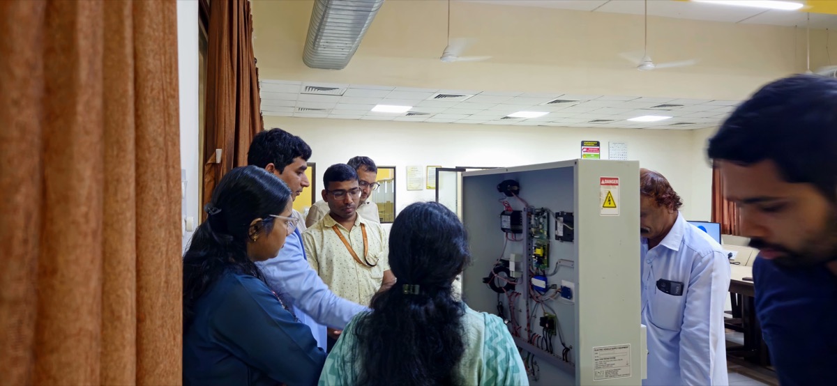
The problem
Portable chargers travel in boots and scooter storage, get dropped, run in hot weather and need cables stored neatly. Many are simple boxes with cables hanging loose. A well-designed housing must carry the cables without strain on terminals, protect the electronics from drops and water, and let heat escape without vents that let water in.
Objectives
- Package an example charger board, heat sink and cable entries in a hand-held housing.
- Design cable storage such as a wrap-around channel or a reel, with strain relief.
- Design a grip and stand-up base so the charger sits safely on the ground.
- Check heat dissipation and drop robustness with hand calculations and simulation where licensed.
- Produce drawings, an assembly sequence and renders.
What you need
Tools and toolboxes
- SOLIDWORKS Part and Assembly — Two-part housing, heat sink, cable channels and placeholder electronics.
- SOLIDWORKS Simulation (Static) — Strain relief and grip loads under cable pull and carrying.
- SOLIDWORKS Simulation Drop Test (optional) — An indicative drop study; Drop Test needs Simulation Professional or Premium, otherwise use an equivalent static impact estimate.
- SOLIDWORKS Flow Simulation (optional) — Heat sink and enclosure temperature under natural convection.
- SOLIDWORKS Visualize — Renders of the charger with cables wrapped and in use.
Software
- SOLIDWORKS 2023 or later
- SOLIDWORKS Simulation
Extra parts and data
- Heat dissipation figure for the example charger electronics — The thermal design needs a realistic loss value, taken from an electronics datasheet or the electronics designer.
Key concepts
- Strain relief
- A feature that transfers cable pull and bending into the housing, so the conductors and terminals inside do not take the load.
- Thermal path
- The route heat takes from components to the outside, through pads, a heat sink and the housing. Each step adds thermal resistance.
- Drop robustness
- The ability to survive being dropped onto a hard floor without cracking or letting components break loose, often improved with ribs, bumpers and secure mounting.
- Bend radius
- Cables have a minimum bend radius; storage features must not force the cable tighter than this.
Step-by-step guide
- 1
Define requirements
Set requirements for an example 3.3 kW portable charger: total mass under a stated target, a 3 m input cable with plug, a 5 m output cable, a status display, operation from minus 5 to 50 degrees Celsius as an example, a splash-resistant IP target and survival of a 1 m drop onto concrete. List cable diameters and minimum bend radii from cable datasheets.
Checkpoint: A requirement list with mass, cable data, IP target, temperature range and drop requirement.
- 2
Package the internals
Model the board, power stage, heat sink and display as placeholder parts. Place hot components near the heat sink, which forms part of the outer housing so heat leaves directly to the air. Position cable entries at one end with room for glands and strain reliefs inside. Keep the centre of mass low and central so the unit stands steady.
Checkpoint: A packaged layout showing component positions, heat sink location and cable entries within the envelope.
- 3
Concept for cable storage
Sketch at least two cable storage concepts: a channel around the housing that the cable wraps into, or a separate carry bag with the housing in the middle. Check the wrap path keeps the cable above its minimum bend radius. Estimate the volume of each cable from its diameter and length to size the channel. Choose one concept with reasons.
Checkpoint: A chosen storage concept with a calculated cable volume and a bend radius check.
- 4
Model the housing
Model a top and bottom shell in a tough plastic such as PC/ABS, with a uniform wall, draft and Lip/Groove for sealing. Integrate the aluminium heat sink as the base or a side face, sealed to the plastic with a gasket. Add a moulded handle or grip recess and four rubber foot pockets. Add internal ribs and bosses to clamp the board on its edges.
Checkpoint: A housing that closes around the internals with Interference Detection clean and the gasket path continuous.
- 5
Design strain reliefs
Design a strain relief at each cable exit: a moulded clamp inside that grips the cable jacket, plus an external flexible boot that limits bending. Check that a cable pull, for example 100 N as an example, is taken by the clamp. Model the clamp as part of the shell or as a separate part screwed to a boss. Check the boot taper with the cable bent to its minimum bend radius, so the cable bends smoothly rather than kinking at the boot tip.
Checkpoint: Cable pull in the strain relief study is carried by the clamp with factor of safety above the target.
- 6
Check the thermal design
Estimate the heat sink temperature by hand from the loss, the heat sink area and a natural convection coefficient, then compare with the component limits. If Flow Simulation is available, model the housing with heat sources, solar load as a hot case and natural convection, and look at component temperatures. Adjust fin size or orientation if needed. Remember that a closed housing in a car boot or scooter storage can be much hotter than ambient, so state the hot case you chose.
Checkpoint: Heat sink temperature below the stated limit in the hot case, with hand and simulation results compared.
- 7
Check drop robustness
If Drop Test is available, run a drop from 1 m onto a rigid floor at the worst orientation, usually a corner, and look at peak stress in the shells and boss loads. Otherwise, estimate impact force from an assumed stopping distance and run an equivalent static case. Add corner bumpers or ribs where stress is high, and treat results as indicative.
Checkpoint: Peak stress after redesign is below the material strength in the indicative case, with the method and its limits stated.
- 8
Plan assembly
Write an assembly sequence: fit cables with strain reliefs into the bottom shell, mount the board, attach the heat sink with thermal pad, fit the gasket and close with screws. Check screw access and that the board can be serviced. Count parts and fastener types and reduce them where you can, for example by using one screw size. Make the assembly sequence into an exploded view configuration so it can be included in the drawing pack and reviewed visually.
Checkpoint: An assembly sequence with part and fastener count, all screws reachable.
- 9
Drawings, renders and report
Produce drawings of the shells with draft notes and sealing details, an assembly drawing with BOM, and renders with the cable stored and in use beside a vehicle. Write a report with requirements, concept choice, thermal and drop results and limitations, stating that IP rating, drop and temperature must be confirmed with physical tests. Include a mass table from Mass Properties, comparing the estimated total mass with the target set at the start.
Checkpoint: A drawing pack, renders and a report with clear limits on simulation results.
Testing & validation
- Cable storage respects the minimum bend radius.
- Strain relief carries the pull load with margin.
- Thermal estimate meets component limits in a hot case.
- Drop or equivalent impact check shows stress below material strength after redesign.
- Interference Detection is clean and assembly access is shown.
Expected results
A portable charger housing design with integrated cable storage, strain reliefs, heat sink path and drop features, supported by thermal and strength checks, drawings and renders.
Take it further
- Print the strain relief and test cable pull with a spring balance.
- Design a wall bracket accessory using the same mounting points.
- Compare two materials for drop robustness with a nonlinear study.
Viva and review questions
Why is the heat sink part of the outer housing?
It gives a short path from the hot components straight to the outside air without needing vents, which helps keep the enclosure sealed.
How did you handle the drop requirement without Drop Test?
I estimated the impact force from mass, drop height and an assumed stopping distance, applied it as a static load at the corner, and treated the result as indicative, with physical testing required.
What does the strain relief protect?
It stops cable pull and bending from reaching the conductors and terminals, which would otherwise loosen or break over time.
Learn it at DIYguru
These DIYguru courses and programmes teach what this project needs.