The level of a signal can be changed, amplifier active devices can be biased with voltage dividers, and voltages can be measured with voltage dividers. Voltage dividers are a feature of both a Wheatstone bridge and a multimeter. In many radios, a potentiometer is used as a variable voltage divider for volume control.
A straightforward circuit known as a voltage divider reduces a large voltage to a smaller one. We can produce an output voltage that is only a small fraction of the input voltage with just two series resistors and an input voltage. One of the most fundamental electronic circuits is the voltage divider. Learning about voltage dividers would be like learning how to spell cat if learning Ohm’s law was like learning the ABCs.
These are examples of potentiometers, which are variable resistors that can be used to make a voltage divider that can be adjusted. We will soon learn more about these.
Voltage Divider Bias Circuit:
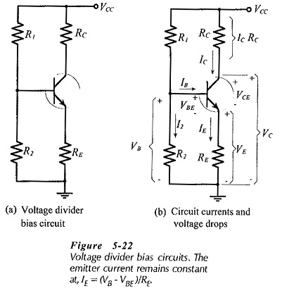
The voltage divider bias method is the most well-known of all the options for providing biasing and stabilization. In this case, biasing is provided by two resistors, R1 and R2, which are connected to VCC. Stabilization is provided by the emitter’s RE resistor.
The name voltage divider comes from the voltage divider shaped by R1 and R2. The base-emitter junction is forward biased by the voltage drop across R2. Under conditions of a zero signal, this results in the flow of the collector current as well as the base current. The voltage divider bias method’s circuit is depicted in the image below.

Let’s say that I1 is the current that passes through resistance R1. Because the base current IB is so small, it is reasonable to assume that the current flowing through R2 is also I1.
Let us now attempt to derive the expressions for collector voltage and current.
From the circuit, it is clear that, IC Collector Current